BE1-BPR Functional Description
4-25
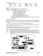
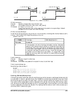
,$ . ,% .
,& . ,1 .
Primary Current
,D ,E
,F ,Q
Secondary Current
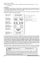
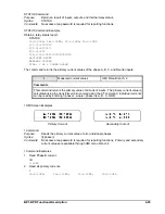
STATUS Command
Purpose:
Returns a report of inputs, outputs, and internal relay status.
Syntax:
STATUS
Comments:
No access area password is required for reporting functions.
STATUS Command Example
Obtain a relay status report.
STATUS
IA=3.00KA; IB=3.00KA; IC=3.00KA; IN=0.00KA
I(1-7)=0100000
T(1-6)=000000
F(1-3)=001
O(A,1-15)=0000000000000000
RECLOSER RESET
BREAKER CLOSED
DIAG: 1 OF 1 TIMER ALARM
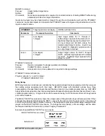
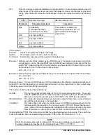
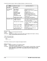
The I command returns the primary current values of the phase A, B, C, and Neutral inputs.
I
Measured current values
HMI Menu Branch: 2
Comments
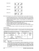
This command returns the primary value of all current inputs. The primary current value is
calculated using the transformer ratio entered using the CT command. Individual currents
can be read by entering I<phase>, where <phase> is A, B, C, OR N.
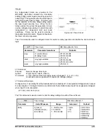
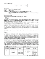
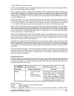
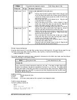
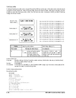
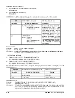
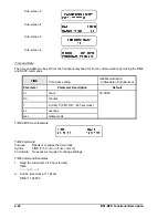
I HMI Screen Examples
I Command
Purpose:
Reads the primary current value of all or individual phases.
Syntsx:
I[<phase>]
Comments:
No access area password is required for reporting functions. Primary and secondary
current values are available through HMI menu branch 2.
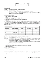
I Command Examples
1.
Read Phase B current.
IB
3.23KA
2.
Read all primary currents.
I
IA=3.23KA; IB=3.23KA; IC=3.23KA; IN=0.00KA
Summary of Contents for BE1-BPR
Page 31: ...BE1 BPR Application 2 17...
Page 42: ...3 4 BE1 BPR Human Machine Interface Figure 3 4 BE1 BPR Relay Vertical Mount Front View...
Page 43: ...BE1 BPR Human Machine Interface 3 5 Figure 3 5 BE1 BPR Relay Vertical Mount Rear View...
Page 49: ...4 6 BE1 BPR Functional Description Figure 4 2 Enhanced BE1 BPR Menu Display Screens...
Page 50: ...BE1 BPR Functional Description 4 7 Figure 4 3 Standard BE1 BPR Menu Display Screens...
Page 94: ...5 4 BE1 BPR BESTlogic Figure 5 1 BESTlogic Function Blocks...
Page 121: ...BE1 BPR Installation 7 3 Figure 7 3 Overall Dimensions Vertical Mount...
Page 122: ...7 4 BE1 BPR Installation Figure 7 4 Overall Dimensions Side View Vertical Mount...
Page 123: ...BE1 BPR Installation 7 5 Figure 7 5 Panel Drilling Diagram Vertical Mount...

