4-28
BE1-BPR Functional Description
%5($.(5 67$786
23(5$7,216
%5($.(5
&/26('
'/2* $
%
&
%.5236
5(6236
2)
%5($.(5 67$786
23(5$7,216
Breaker Status
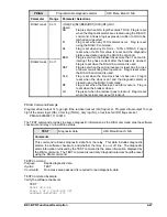
Breaker status information is contained in three logs for diagnostic purposes. They are the breaker
operations log, the breaker resistor operations log, and the breaker contact duty log (enhanced relays only).
Breaker status information may also be viewed or configured through a communication port using the DLOG,
BKRCON, BKRRES, BKROPS, and STATUS commands.
Breaker Status Menu Screens
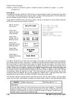
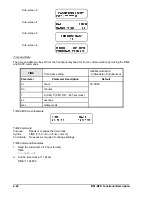
An example of typical breaker status screens are provided below.
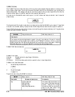
BREAKER STATUS
Menu Screen
Sub-screen 1
Breaker Status Screen
Sub-screen 2 Log
(Enhanced Relays Only)
Contact Duty
Sub-screen 3
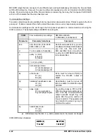
Breaker Operations and
Breaker Resistor Operations
Breaker Status Screen
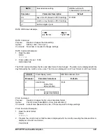
The breaker status screen shows the current position of the breaker (OPEN/CLOSED) based on the logic
defined by the BKROPS command. Breaker position is also reported by the STATUS command.
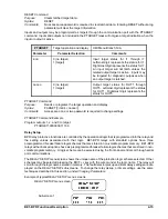
BKROPS
Breaker operations status
HMI Menu Branch: 3
Parameter
Unit of Measure
Range
Increment
Default
#operations
breaker operations
0 - 99,999
1
00,000
52b contact logic
N/A
N/A
N/A
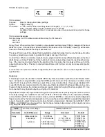
/I1
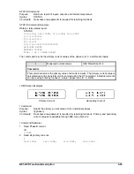
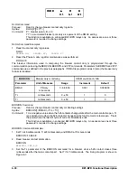
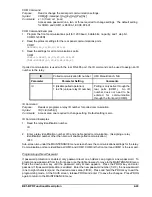
BKROPS HMI Screen Example
BKROPS Command
Purpose:
Read or change breaker operations data.
Syntax:
BKROPS[=<#operations>,<52a/b contact logic>]
Comments:
An access area one or three password is required to change settings. 52a/b contact logic can
be defined using any contact sensing input. The logic defines when the breaker is open.
BKROPS Command Example
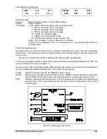
Set the breaker operations counter at zero and use contact input 2 to sense when the breaker opens (52a
contact finger).
BKROPS=0,/I2
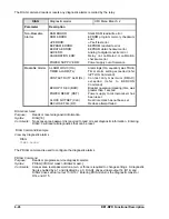
Breaker Contact Duty Diagnostics (Enhanced Relays Only)
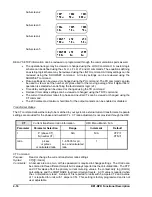
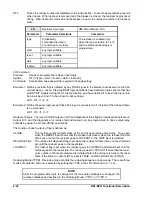
Breaker contact duty log, DLOG, is stored in non-volatile memory and contains the approximate duty or
contact wear on each pole (phase) of the breaker represented as a percentage of a maximum, DMAX. A
Summary of Contents for BE1-BPR
Page 31: ...BE1 BPR Application 2 17...
Page 42: ...3 4 BE1 BPR Human Machine Interface Figure 3 4 BE1 BPR Relay Vertical Mount Front View...
Page 43: ...BE1 BPR Human Machine Interface 3 5 Figure 3 5 BE1 BPR Relay Vertical Mount Rear View...
Page 49: ...4 6 BE1 BPR Functional Description Figure 4 2 Enhanced BE1 BPR Menu Display Screens...
Page 50: ...BE1 BPR Functional Description 4 7 Figure 4 3 Standard BE1 BPR Menu Display Screens...
Page 94: ...5 4 BE1 BPR BESTlogic Figure 5 1 BESTlogic Function Blocks...
Page 121: ...BE1 BPR Installation 7 3 Figure 7 3 Overall Dimensions Vertical Mount...
Page 122: ...7 4 BE1 BPR Installation Figure 7 4 Overall Dimensions Side View Vertical Mount...
Page 123: ...BE1 BPR Installation 7 5 Figure 7 5 Panel Drilling Diagram Vertical Mount...

