4-32
BE1-BPR Functional Description
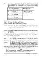
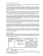
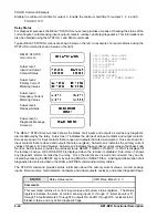
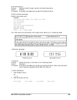
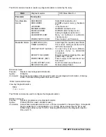
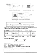
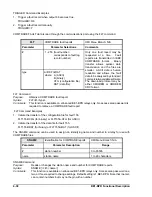
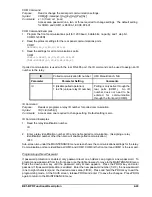
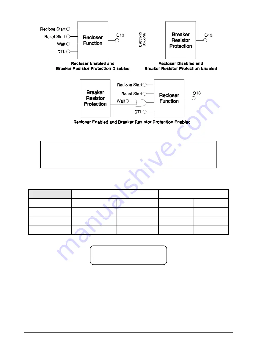
Figure 4-8. Output 13 Logic
NOTE
If Ires is programmed, then the DUTY LOG uses that value in current (I) calculations
instead of ( CTP*I[p][n] ) because it would be difficult to separate the arcing current from
the fault current prior to the resistor being inserted.
%.5236
5(6236
2)
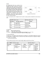
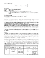
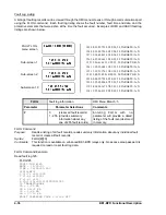
Breaker information used in the breaker resistor diagnostics are programmed using the BKRRES command.
If MAXOPS is programmed to zero, the resistor heating diagnostic is disabled.
BKRRES
Breaker resistor monitoring data
HMI Menu Branch: 3
Parameter
Unit of Measure
Range
Increment
Default
MAXOPS
breaker operations
0 - 10
1
00,000
reset
minutes
0 - 255
1
0
Ires
primary amperes
0.000 - 6.8E38
0.001
0.000E+00
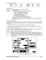
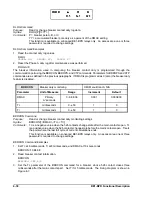
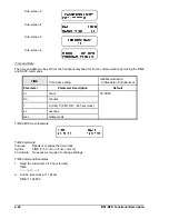
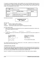
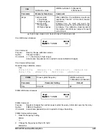
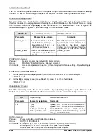
BKRRES HMI Screen Example
BKRRES Command
Purpose:
Read or change breaker resistor monitoring data.
Syntax:
BKRRES[=<MAXOPS>,<reset>,<Ires>]
Comments:
An access area one or three password is required to change settings.
BKRRES Command Example
Set Ires at 500 amperes, reset_time at 15 minutes, and MAXOPS at 4.
BKRRES=4,15,500
Summary of Contents for BE1-BPR
Page 31: ...BE1 BPR Application 2 17...
Page 42: ...3 4 BE1 BPR Human Machine Interface Figure 3 4 BE1 BPR Relay Vertical Mount Front View...
Page 43: ...BE1 BPR Human Machine Interface 3 5 Figure 3 5 BE1 BPR Relay Vertical Mount Rear View...
Page 49: ...4 6 BE1 BPR Functional Description Figure 4 2 Enhanced BE1 BPR Menu Display Screens...
Page 50: ...BE1 BPR Functional Description 4 7 Figure 4 3 Standard BE1 BPR Menu Display Screens...
Page 94: ...5 4 BE1 BPR BESTlogic Figure 5 1 BESTlogic Function Blocks...
Page 121: ...BE1 BPR Installation 7 3 Figure 7 3 Overall Dimensions Vertical Mount...
Page 122: ...7 4 BE1 BPR Installation Figure 7 4 Overall Dimensions Side View Vertical Mount...
Page 123: ...BE1 BPR Installation 7 5 Figure 7 5 Panel Drilling Diagram Vertical Mount...


