4-36
BE1-BPR Functional Description
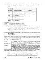
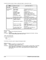
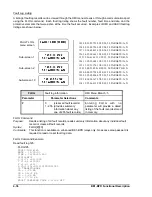
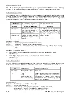
)$8/7 /2* )/2*
129 08:33:22.751 02/22/94, 50 TARGETS=A,N
128 08:33:09.796 02/22/94, 50 TARGETS=A,N
127 19:34:48.467 01/30/94, 50 TARGETS=A,N
126 14:25:09.663 12/20/93, 50 TARGETS=A,N
125 12:26:41.653 11/25/93, 50 TARGETS=B,N
124 11:19:19.684 11/01/93, 50 TARGETS=A,N
123 11:19:15.176 11/01/93, 50 TARGETS=A,N
122 12:08:23.488 10/09/93, 50 TARGETS=B,N
121 00:00:22.758 09/18/93, 50 TARGETS=A,N
120 23:55:09.896 07/22/93, 50 TARGETS=A,N
119 18:34:58.367 07/03/93, 50 TARGETS=A,N
118 13:25:06.613 05/20/93, 50 TARGETS=A,N
7$5*(76 $1
7$5*(76 $1
7$5*(76 $1
Fault Log Listing
A listing of fault log records can be viewed through the HMI menu screens or through a communications port
using the FLOG command. Each fault log listing shows the fault number, fault time and date, and the
protective elements that were active at the time the fault occurred. Examples of HMI and ASCII fault log
listings are shown below.
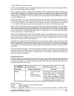
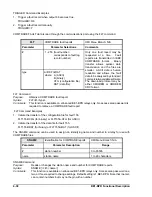
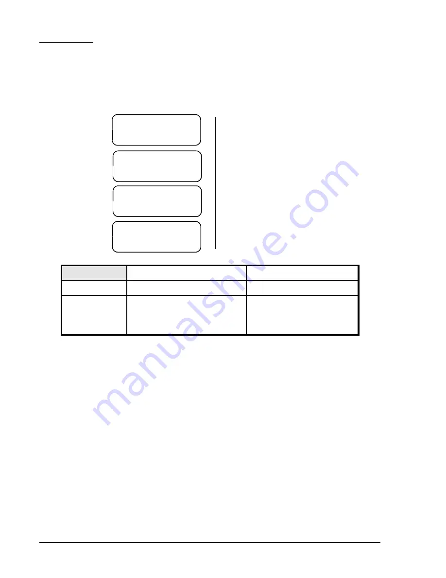
FAULT LOG
menu screen
Sub-screen 1
Sub-screen 2
Sub-screen 10
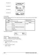
FLOG
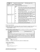
Fault log information
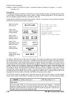
HMI Menu Branch: 5
Parameter
Parameter Selections
Comments
#
0
(clears all fault records)
1 - 255 (provides summary
information about any
one of 255 fault records)
Entering FLOG with no
parameter will provide a dated
listing of the fault records stored
in memory.
FLOG Command
Purpose:
Reads a listing of all fault records, reads summary information about any individual fault
record or clears all fault records.
Syntax:
FLOG[#][=0]
Comments:
This function is available on enhanced BE1-BPR relays only. No access area password is
required to read or reset fault log data.
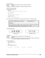
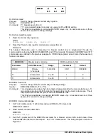
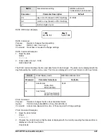
FLOG Command Example
Read fault log 125.
FLOG125
FAULT LOG #125
DATE = 11/25/93
TIME = 12:26:41.653
LOGIC=BFL1
I (1-7) =0111000
T (1-6) =100000
F (1-3) =111
O (A,1-15)=0111101000011001
50 TARGETS=NONE
IA = 1.25 KA
IB = 38.31 KA
IC = 1.28 KA
IN = 37.13 KA
FAULT CLEARING TIME = 0.164 SEC
Summary of Contents for BE1-BPR
Page 31: ...BE1 BPR Application 2 17...
Page 42: ...3 4 BE1 BPR Human Machine Interface Figure 3 4 BE1 BPR Relay Vertical Mount Front View...
Page 43: ...BE1 BPR Human Machine Interface 3 5 Figure 3 5 BE1 BPR Relay Vertical Mount Rear View...
Page 49: ...4 6 BE1 BPR Functional Description Figure 4 2 Enhanced BE1 BPR Menu Display Screens...
Page 50: ...BE1 BPR Functional Description 4 7 Figure 4 3 Standard BE1 BPR Menu Display Screens...
Page 94: ...5 4 BE1 BPR BESTlogic Figure 5 1 BESTlogic Function Blocks...
Page 121: ...BE1 BPR Installation 7 3 Figure 7 3 Overall Dimensions Vertical Mount...
Page 122: ...7 4 BE1 BPR Installation Figure 7 4 Overall Dimensions Side View Vertical Mount...
Page 123: ...BE1 BPR Installation 7 5 Figure 7 5 Panel Drilling Diagram Vertical Mount...

