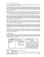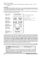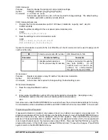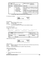
BE1-BPR Functional Description
4-37
Fault Summary
Detailed information about specific faults is available through the communications ports using the FLOG
command. Entering FLOGx, where x is the fault number, provides a detailed summary of fault x. The
information listed below is provided in each fault summary.
Fault timing is provided to millisecond resolution.
Fault current for each phase is provided.
Status of all inputs and outputs at the time the fault occurred.
Fault clearing time. (Defined as the time from when the fault was triggered to when the instanta-
neous fault detector(s) drop out.)
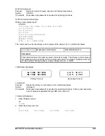
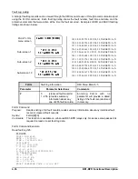
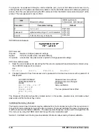
An example of a fault log report is shown below:
FAULT LOG #125
DATE =11/25/93
TIME =12:26:41.653
LOGIC =BFL1
I(1-7)=0111000
T(1-6)=100000
F(1-3)=111
O(A,1-15)=0111101000011001
50 TARGETS= B,N
IA =1.25 kA
IB =38.31 kA
IC =1.28 kA
IN =37.13 kA
FAULT CLEARING TIME = 0.164 sec
Oscillographic Data Acquisition
An oscillographic data record is triggered when the trigger logic defined by the TRIGGER command
becomes TRUE. Typically, a fault record is taken whenever a contact input is recognized that could trigger
the BFO. The fault trigger is reset and re-armed after the TRIGGER definition becomes FALSE.
The fault data recorded is as follows:
Fault log number (1-255).
Date and time of the start of fault data to one millisecond resolution.
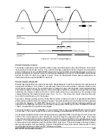
Twenty cycles of sampled data (four cycles pre-fault and sixteen cycles post-fault) consisting of the
A/D data values of phase and neutral currents and status of all contact inputs and outputs, virtual
outputs and timer/counters. The fault data sampling rate is twelve samples per cycle. Analog data
is bandwidth limited to 200 hertz because of the anti-aliasing low-pass filter.
Fault data format follows the COMTRADE Standard (
IEEE C37.111-1991: Common Format for
Transient Data Exchange (COMTRADE) for Power Systems).
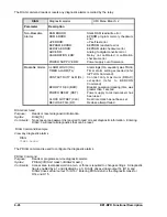
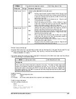
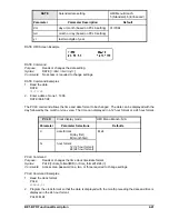
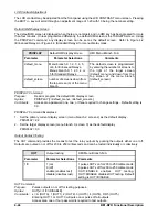
TRIGGER
Oscillograph trigger
HMI Menu Branch: N/A
Parameter
Comments
logic term
Any logic term can be used to define the logic conditions that will
automatically trigger a fault record.
Y
Entering TRIGGER=Y will trigger a fault record through a
communication port. No password access is required.
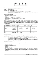
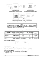
TRIGGER Command
Purpose:
Reads or changes the trigger logic or triggers a fault record.
Syntax:
TRIGGER[=<logic term>/Y]
Comments:
This function is available on enhanced BE1-BPR relays only. Access area password one,
two, or three is required to change settings. No password access is needed to trigger a
fault record.
Summary of Contents for BE1-BPR
Page 31: ...BE1 BPR Application 2 17...
Page 42: ...3 4 BE1 BPR Human Machine Interface Figure 3 4 BE1 BPR Relay Vertical Mount Front View...
Page 43: ...BE1 BPR Human Machine Interface 3 5 Figure 3 5 BE1 BPR Relay Vertical Mount Rear View...
Page 49: ...4 6 BE1 BPR Functional Description Figure 4 2 Enhanced BE1 BPR Menu Display Screens...
Page 50: ...BE1 BPR Functional Description 4 7 Figure 4 3 Standard BE1 BPR Menu Display Screens...
Page 94: ...5 4 BE1 BPR BESTlogic Figure 5 1 BESTlogic Function Blocks...
Page 121: ...BE1 BPR Installation 7 3 Figure 7 3 Overall Dimensions Vertical Mount...
Page 122: ...7 4 BE1 BPR Installation Figure 7 4 Overall Dimensions Side View Vertical Mount...
Page 123: ...BE1 BPR Installation 7 5 Figure 7 5 Panel Drilling Diagram Vertical Mount...

