4-38
BE1-BPR Functional Description
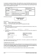
TRIGGER Command Examples
1.
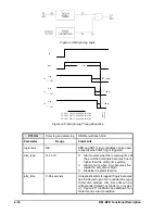
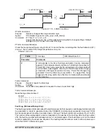
Trigger a fault record when output 6 becomes true.
TRIGGER=O6
2.
Trigger a fault record manually.
TRIGGER=Y
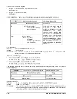
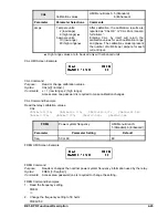
COMTRADE FAULT data is read through the communications port using the FLT command.
FLT
COMTRADE fault reports
HMI Menu Branch: N/A
Parameter
Parameter Selections
Comments
#
1 - 255 (fault number -
corresponds to fault log
record number)
Only one fault report may be
requested at a time. Fault
reports are transmitted in IEEE
COMTRADE format. Binary
transfer allows quicker data
transmission and the files are
smaller. ASCII data is human
readable and allows the fault
data to be analyzed by standard,
commercially available software.
The download protocol may be
either XMODEM or XMODEM
CRC format.
type
A/B.CFG/DAT
where: A (ASCII)
B (binary)
CFG (configuration file)
DAT (data file)
FLT Command
Purpose:
Obtains a COMTRADE fault report.
Syntax:
FLT<#><type>
Comments:
This function is available on enhanced BE1-BPR relays only. No access area password is
required to retrieve a COMTRADE fault report.
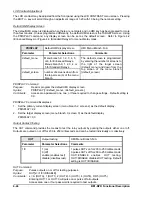
FLT Command Examples
1.
Initiate the transfer of the configuration file for fault 155.
FLT155B.CFG (for binary) or FLT155A.CFG (for ASCII)
2.
Initiate the transfer of the data file for fault 155.
FLT155B.DAT (for binary) or FLT155A.DAT (for ASCII)
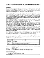
The SNAME command can be used to assign an identifying name and number to a relay for use with
COMTRADE files.
SNAME
Identification for COMTRADE reports
HMI Menu Branch: N/A
Parameter
Parameter Description
Range
#
station number
0 to 65535
name
station name
1 to 29 characters
SNAME Command
Purpose:
Reads or changes the station name and number for COMTRADE reports.
Syntax:
SNAME [=<#>,<name>]
Comments:
This function is available on enhanced BE1-BPR relays only.
Access area password one,
two, or three required to change settings. Default setting is 1,BE1-BPR. Note that <name>
can contain numbers but may not begin with a number.
Summary of Contents for BE1-BPR
Page 31: ...BE1 BPR Application 2 17...
Page 42: ...3 4 BE1 BPR Human Machine Interface Figure 3 4 BE1 BPR Relay Vertical Mount Front View...
Page 43: ...BE1 BPR Human Machine Interface 3 5 Figure 3 5 BE1 BPR Relay Vertical Mount Rear View...
Page 49: ...4 6 BE1 BPR Functional Description Figure 4 2 Enhanced BE1 BPR Menu Display Screens...
Page 50: ...BE1 BPR Functional Description 4 7 Figure 4 3 Standard BE1 BPR Menu Display Screens...
Page 94: ...5 4 BE1 BPR BESTlogic Figure 5 1 BESTlogic Function Blocks...
Page 121: ...BE1 BPR Installation 7 3 Figure 7 3 Overall Dimensions Vertical Mount...
Page 122: ...7 4 BE1 BPR Installation Figure 7 4 Overall Dimensions Side View Vertical Mount...
Page 123: ...BE1 BPR Installation 7 5 Figure 7 5 Panel Drilling Diagram Vertical Mount...

