4-42
BE1-BPR Functional Description
&20)
&205
. 1
1
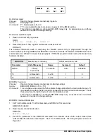
BE1-BPR relays that are connected to an IRIG-B source will automatically synchronize the time and date
with the IRIG-B source. However, the year must be set manually since it is not included in the IRIG-B data
stream. Once all components of the time and date are received by the relay, the front panel CLOCK LED
will turn off to indicate that the clock has been set.
Communications Settings
Two communication ports are available, but only one port can be used at a time. Priority is given to the front
panel port. If data is received from both ports at the same time, an error response is generated.
Communication settings can be set through the front panel keyboard or a communication port using the
COM command. The default setting is 96008N1 for both ports.
COM
Communication port settings
HMI Menu Branch:
5 (Standard), 6 (Enhanced)
U
Parameter
Parameter Selections
Comments
rate
300, 600, 900, 1200, 2400,
4800, 9600, or 19K
Not all combinations of d, p, and s
are allowed. Allowed combinations
are: 7O1, 7E1, 7N2, 8O1, 8E1,
8N1, and 8N2. Note: d must be 8
in order for COMTRADE fault data
to be transmitted.
d
7 or 8 (number of data bits)
p
parity: O (odd)
E (even)
N (none)
s
1 or 2 (stop bits)
Ay
acknowledge mode:
A1 (acknowledge on)
A0 (acknowledge off)
Ey
echo mode:
E1 (on)
E0 (off)
Echo must be turned off (E0) to
enable the RS-485 output at
COM1.
Hy
hardware handshake mode:
H1 (on)
H0 (off)
Handshaking must be turned off
(H0) to enable the RS-485 output
at COM1.
Pyy
page mode:
P0 (no pagination)
Pyy (set page length)
Pyy setting range is P05 to P99.
When the page mode setting is not
zero, then any command whose
output exceeds length Pyy will
pause after the given number of
lines are printed. The operator will
be prompted to press any key to
continue the output.
Xy
handshake mode:
X1 (on)
X0 (off)
U
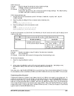
HMI allows only the rate, d, p, and s parameters to be viewed or changed.
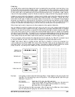
COM HMI Screen Example
Summary of Contents for BE1-BPR
Page 31: ...BE1 BPR Application 2 17...
Page 42: ...3 4 BE1 BPR Human Machine Interface Figure 3 4 BE1 BPR Relay Vertical Mount Front View...
Page 43: ...BE1 BPR Human Machine Interface 3 5 Figure 3 5 BE1 BPR Relay Vertical Mount Rear View...
Page 49: ...4 6 BE1 BPR Functional Description Figure 4 2 Enhanced BE1 BPR Menu Display Screens...
Page 50: ...BE1 BPR Functional Description 4 7 Figure 4 3 Standard BE1 BPR Menu Display Screens...
Page 94: ...5 4 BE1 BPR BESTlogic Figure 5 1 BESTlogic Function Blocks...
Page 121: ...BE1 BPR Installation 7 3 Figure 7 3 Overall Dimensions Vertical Mount...
Page 122: ...7 4 BE1 BPR Installation Figure 7 4 Overall Dimensions Side View Vertical Mount...
Page 123: ...BE1 BPR Installation 7 5 Figure 7 5 Panel Drilling Diagram Vertical Mount...


