4-44
BE1-BPR Functional Description
3$66:25' (175<
3: $%&%
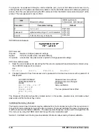
To program a new password through a communications port, you must first obtain access level one by
entering Password 1 if password protection is enabled. Use the ACCESS command to obtain programming
access. Enter the new password using the PW command. Enter the SAVE command and answer Y at the
prompt. The new password is now in effect.
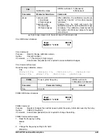
PW
Password settings
HMI Menu Branch:
5 (Standard), 6 (Enhanced)
Parameter
Parameter Setting
Default
#
1, 2, 3, or 4
PW1=0,B
PW2=0,B
PW3=0,B
PW4=0,B
password
alphanumeric string of 1 to 8 characters
access
F (front), R (rear), or B (both)
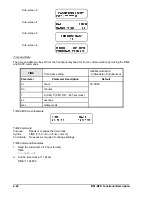
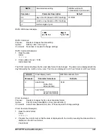
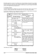
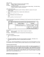
PW HMI Screen Example
PW Command
Purpose:
Reads or changes password settings
Syntax:
PW [<#>[=<password>,<access(F/R/B)>]]
Comments:
Access area one password is required to change password settings
PW Command Examples
1.
Read the current passwords, assuming that the area one password has already been entered using
the ACCESS=<password> command.
PW
PW1=ABC,B; PW2=123, FPW3=XYZ,F; PW4=BPR,F
2.
Change Password 2 from front access and no password to front and rear access with a password of
RELAYGRP
>ACCESS=OPENUP
Password level one entered
>PW2=RELAYGRP,B
Password level two changed
>SAVE
Save data
ARE YOU SURE (Y/N) ?
Y
Relay verification.
RELAY OFF_LINE
CHANGES SAVED
The new password takes effect.
RELAY ON_LINE
>
The
Password Protection sub-section, located earlier in this section, provides more information about
passwords and the functions they control.
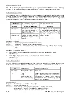
Calibrating the Analog Channels
The Analog (current input) channels may be calibrated from the front panel using the CAL menu screen or
through the communications port using the CAL command. For proper calibration the power line frequency
must be known and set before calibration. The power system frequency can be read or changed from the
CAL menu or by using the FREQ command through the communications port.
Section 8,
Calibration and Testing provides detailed information about analog channel calibration.
Summary of Contents for BE1-BPR
Page 31: ...BE1 BPR Application 2 17...
Page 42: ...3 4 BE1 BPR Human Machine Interface Figure 3 4 BE1 BPR Relay Vertical Mount Front View...
Page 43: ...BE1 BPR Human Machine Interface 3 5 Figure 3 5 BE1 BPR Relay Vertical Mount Rear View...
Page 49: ...4 6 BE1 BPR Functional Description Figure 4 2 Enhanced BE1 BPR Menu Display Screens...
Page 50: ...BE1 BPR Functional Description 4 7 Figure 4 3 Standard BE1 BPR Menu Display Screens...
Page 94: ...5 4 BE1 BPR BESTlogic Figure 5 1 BESTlogic Function Blocks...
Page 121: ...BE1 BPR Installation 7 3 Figure 7 3 Overall Dimensions Vertical Mount...
Page 122: ...7 4 BE1 BPR Installation Figure 7 4 Overall Dimensions Side View Vertical Mount...
Page 123: ...BE1 BPR Installation 7 5 Figure 7 5 Panel Drilling Diagram Vertical Mount...

