BE1-BPR Functional Description
4-45
&$/
)5(4
5$1*(/+
&$/
)5(4
5$1*(/+
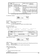
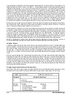
CAL
Calibration values
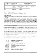
HMI Menu Branch: 5 (Standard)
6 (Enhanced)
Parameter
Parameter Selections
Comments
amps
1 ampere units:
2 (low range)
8 (high range)
U
5 ampere units:
10 (low range)
40 (high range)
U
After calibration, the calibration results are
reported as “CAL OK” or “CAL FAIL <reason
for failure>”.
Entering CAL by itself will return the
calibration values for each calibration range
and phase. The calibration values represent
the number of A/D bits per ampere for each
current input.
U
High range values are to be used only with enhanced units.
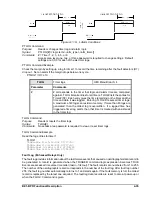
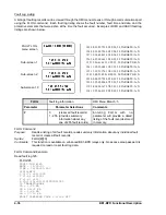
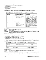
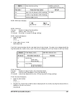
CAL HMI Screen Example
CAL Command
Purpose:
Read or change calibration values.
Syntax:
CAL[x][=<amps>]
Comments:
x = 1 (low range), 2 (high range)
Access area one password is required to make calibration changes.
CAL Command Example
Read the relay calibration values.
CAL
CAL1A=140.766; CAL1B=141.110; CAL1C=143.237; CAL1N=141.543
CAL2A=7.076; CAL2B=7.070; CAL2C=7.083; CAL2N=7.064
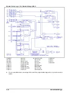
FREQ
Power system frequency
HMI Menu Branch:
5 (Standard), 6 (Enhanced)
Parameter
Parameter Setting
Default
freq
50 or 60
60
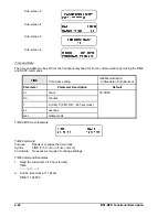
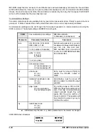
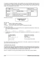
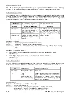
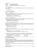
FREQ HMI Screen Example
FREQ Command
Purpose:
Reads or changes the nominal power system frequency information used by the relay.
Syntax:
FREQ [=<freq(hz)>]
Comments:
Access area password one is required to change the setting.
FREQ Command Examples
1.
Read the frequency setting.
FREQ
60
2.
Change the frequency setting to 50 hertz.
FREQ=50
Summary of Contents for BE1-BPR
Page 31: ...BE1 BPR Application 2 17...
Page 42: ...3 4 BE1 BPR Human Machine Interface Figure 3 4 BE1 BPR Relay Vertical Mount Front View...
Page 43: ...BE1 BPR Human Machine Interface 3 5 Figure 3 5 BE1 BPR Relay Vertical Mount Rear View...
Page 49: ...4 6 BE1 BPR Functional Description Figure 4 2 Enhanced BE1 BPR Menu Display Screens...
Page 50: ...BE1 BPR Functional Description 4 7 Figure 4 3 Standard BE1 BPR Menu Display Screens...
Page 94: ...5 4 BE1 BPR BESTlogic Figure 5 1 BESTlogic Function Blocks...
Page 121: ...BE1 BPR Installation 7 3 Figure 7 3 Overall Dimensions Vertical Mount...
Page 122: ...7 4 BE1 BPR Installation Figure 7 4 Overall Dimensions Side View Vertical Mount...
Page 123: ...BE1 BPR Installation 7 5 Figure 7 5 Panel Drilling Diagram Vertical Mount...

