


A
Block
logic input is provided to each function and can be used to disable the function. When this
expression is TRUE, the function is disabled by forcing the outputs to logic zero and resetting the timers
to zero. For example, this could be used similar to a torque control contact on an electromechanical relay.
Each instantaneous overcurrent function has a pickup and a time delay setting. When the measured
current is above the pickup threshold, the pickup logic output, 50TPPU (for example) = TRUE and the
timer is started. If the current stays above pickup for the time delay, the trip logic output, 50TPT (for
example) = TRUE. If the current falls below the dropout ratio, which is 95%, the timer is reset to zero.
The phase overcurrent protective functions include three independent comparators and timers, one for
each phase. If the current is above the pickup setting for any one phase, the pickup logic output is
asserted and if the trip condition is TRUE for any one phase, the trip logic output is asserted.
If the target is enabled for the function, the target reporting function will record a target for the appropriate
phase when the protective function trip output is TRUE and the fault recording function trip logic
expression is TRUE. See Section 6,
Reporting and Alarm Functions, Fault Reporting Functions,
for more
details on the target reporting function.
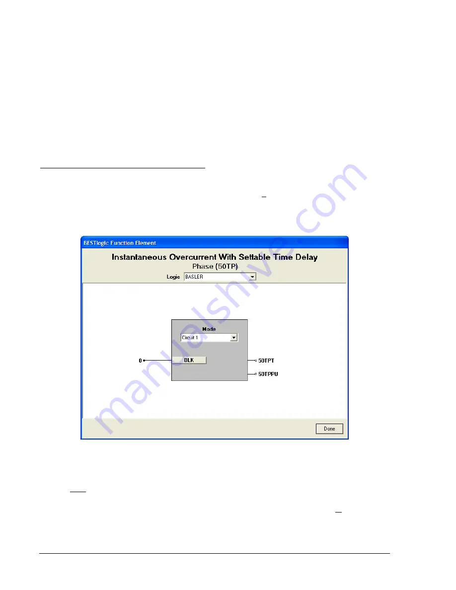
BESTlogic Settings for Instantaneous Overcurrent
BESTlogic settings are made from the
BESTlogic Function Element
screen in BESTCOMS. Figure 4-21
illustrates the BESTCOMS screen used to select BESTlogic settings for the 50T elements. To open the
BESTlogic Function Element
screen, select
Overcurrent
from the
Screens
pull-down menu. Then select
the
50T/150T, 250T/350T, 450T/550T,
or
650T/750T
tab. Open the
BESTlogic Function Element
screen
for the desired element by selecting the
BESTlogic
button corresponding with the desired element.
Alternately, these settings can be made using the SL-x50T ASCII commands (where x = blank, 1, 2, 3, 4,
5, 6, or 7).
Figure 4-21. BESTlogic Function Element Screen, Phase (50TP)
At the top center of the
BESTlogic Function Element
screen is a pull-down menu labeled
Logi
c. This
menu allows viewing of the BESTlogic settings for each preprogrammed logic scheme. A custom logic
scheme must be created and selected in the
Logic
pull-down menu at the top of the screen before
BESTlogic settings can be changed. See Section 7,
BESTlogic Programmable Logic
.
Enable the 50T, 150T, 250T, etc. function by selecting its mode of operation from the
Mode
pull-down
menu. To connect the element's inputs, select the button for the corresponding input in the
BESTlogic
Function Element
screen. The
BESTlogic Expression Builder
screen will open. Select the expression type
to be used. Then, select the BESTlogic variable, or series of variables to be connected to the input.
Select
Save
when finished to return to the
BESTlogic Function Element
screen. For more details on the
4-24
BE1-CDS240 Protection and Control
9365200990 Rev F
Summary of Contents for BE1-CDS240
Page 2: ......
Page 8: ...vi BE1 CDS240 Introduction 9365200990 Rev F This page intentionally left blank ...
Page 38: ...1 28 BE1 CDS240 General Information 9365200990 Rev F This page intentionally left blank ...
Page 40: ...ii BE1 CDS240 Quick Start 9365200990 Rev F This page intentionally left blank ...
Page 152: ...ii BE1 CDS240 Metering 9365200990 Rev F This page intentionally left blank ...
Page 226: ...iv BE1 CDS240 Application 9365200990 Rev F This page intentionally left blank ...
Page 286: ...ii BE1 CDS240 Security 9365200990 Rev F This page intentionally left blank ...
Page 290: ...9 4 BE1 CDS240 Security 9365200990 Rev F This page intentionally left blank ...
Page 292: ...ii BE1 CDS240 Human Machine Interface 9365200990 Rev F This page intentionally left blank ...
Page 306: ...10 14 BE1 CDS240 Human Machine Interface 9365200990 Rev F This page intentionally left blank ...
Page 308: ...ii BE1 CDS240 ASCII Command Interface 9365200990 Rev F This page intentionally left blank ...
Page 342: ...11 34 BE1 CDS240 ASCII Command Interface 9365200990 Rev F This page intentionally left blank ...
Page 349: ...Figure 12 5 Horizontal Rack Mount Front View 9365200990 Rev F BE1 CDS240 Installation 12 5 ...
Page 361: ...Figure 12 17 Typical DC Connection Diagrams 9365200990 Rev F BE1 CDS240 Installation 12 17 ...
Page 372: ...12 28 BE1 CDS240 Installation 9365200990 Rev F This page intentionally left blank ...
Page 468: ...13 92 BE1 CDS240 Testing and Maintenance 9365200990 Rev F This page intentionally left blank ...
Page 512: ...14 42 BE1 CDS240 BESTCOMS Software 9365200990 Rev F This page intentionally left blank ...
Page 544: ...ii BE1 CDS240 Terminal Communication 9365200990 Rev F This page intentionally left blank ...
Page 550: ...ii BE1 CDS240 Settings Calculations 9365200990 Rev F This page intentionally left blank ...
Page 578: ...D 28 BE1 CDS240 Settings Calculations 9365200990 Rev F This page intentionally left blank ...
Page 579: ......


