SECTION 6
REPORTING AND ALARM
FUNCTIONS
INTRODUCTION
This section describes all available reports from the BE1-CDS240 Current Differential System and how
they are set and retrieved. All alarm functions are also described along with how major and minor alarms
are programmed (or mapped).
RELAY IDENTIFIER INFORMATION
It is important to attach (label) meaningful names to the relays and the relay reports. To provide this
feature, BE1-CDS240 relays have four relay identification fields: Relay ID, Station ID, User Label 1, and
User Label 2. These fields are used in the header information lines of the Fault Reports, the
Oscillographic Records, and the Sequence of Events Recorder (SER) Reports. Each of these four ID
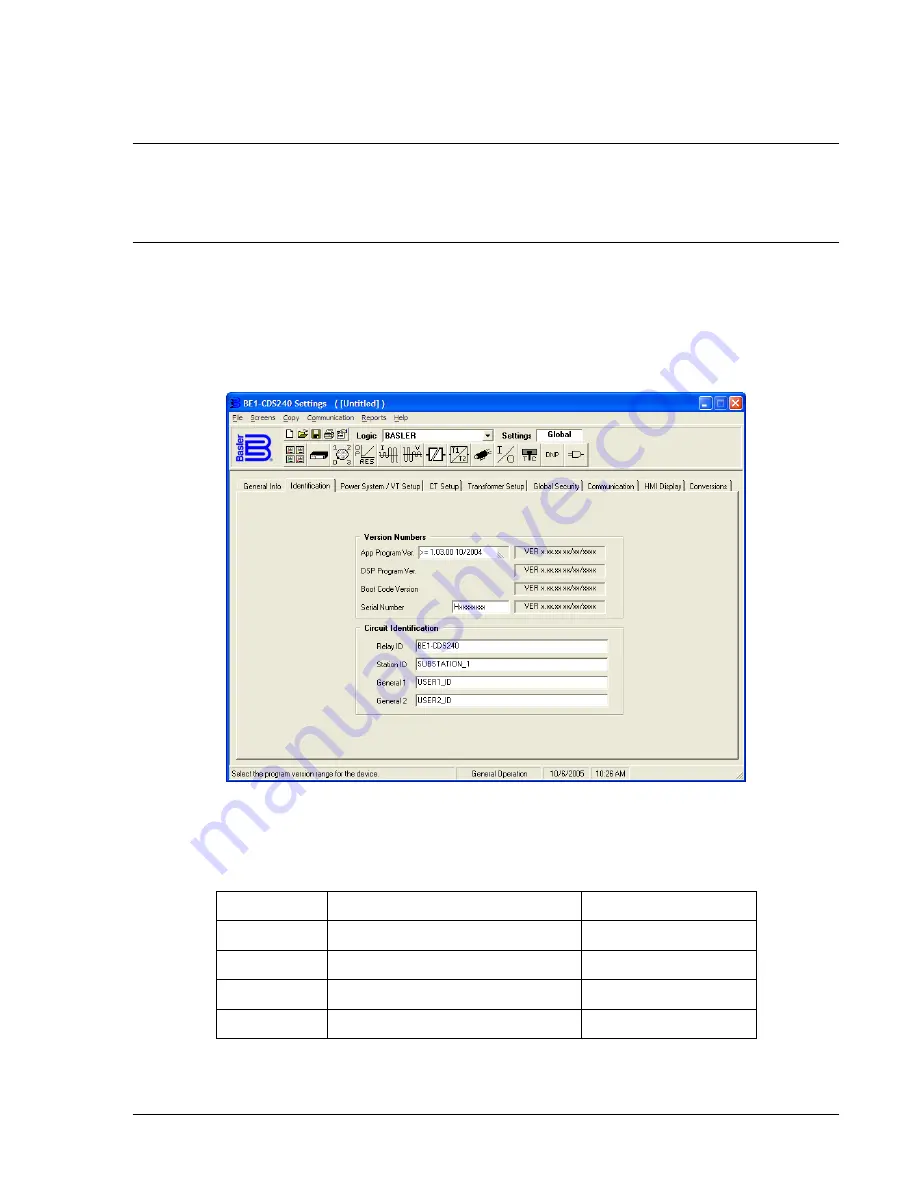
fields may be up to 30 alpha/numeric characters long. Figure 6-1 illustrates the BESTCOMS screen used
to change these settings. Alternately, settings may be made using the SG-ID ASCII command.
Figure 6-1. General Operation Screen, Identification Tab
To change these, delete the old label from the cell and type the new label. Identification settings are
summarized in Table 6-1.
Table 6-1. Circuit Identification Settings
Setting Parameters
Default
Relay ID
30 characters maximum
BE1-CDS240
Station ID
30 characters maximum
SUBSTATION_1
General 1
30 characters maximum
USER1_ID
General 2
30 characters maximum
USER2_ID
No spaces are allowed in labels; any spaces used in the labels are stripped when the label change is
saved. Use the character “_” (Shift + Underscore) to create a break in characters. An example of this is
“SUBSTATION_1”.
9365200990 Rev F
BE1-CDS240 Reporting and Alarm Functions
6-1
Summary of Contents for BE1-CDS240
Page 2: ......
Page 8: ...vi BE1 CDS240 Introduction 9365200990 Rev F This page intentionally left blank ...
Page 38: ...1 28 BE1 CDS240 General Information 9365200990 Rev F This page intentionally left blank ...
Page 40: ...ii BE1 CDS240 Quick Start 9365200990 Rev F This page intentionally left blank ...
Page 152: ...ii BE1 CDS240 Metering 9365200990 Rev F This page intentionally left blank ...
Page 226: ...iv BE1 CDS240 Application 9365200990 Rev F This page intentionally left blank ...
Page 286: ...ii BE1 CDS240 Security 9365200990 Rev F This page intentionally left blank ...
Page 290: ...9 4 BE1 CDS240 Security 9365200990 Rev F This page intentionally left blank ...
Page 292: ...ii BE1 CDS240 Human Machine Interface 9365200990 Rev F This page intentionally left blank ...
Page 306: ...10 14 BE1 CDS240 Human Machine Interface 9365200990 Rev F This page intentionally left blank ...
Page 308: ...ii BE1 CDS240 ASCII Command Interface 9365200990 Rev F This page intentionally left blank ...
Page 342: ...11 34 BE1 CDS240 ASCII Command Interface 9365200990 Rev F This page intentionally left blank ...
Page 349: ...Figure 12 5 Horizontal Rack Mount Front View 9365200990 Rev F BE1 CDS240 Installation 12 5 ...
Page 361: ...Figure 12 17 Typical DC Connection Diagrams 9365200990 Rev F BE1 CDS240 Installation 12 17 ...
Page 372: ...12 28 BE1 CDS240 Installation 9365200990 Rev F This page intentionally left blank ...
Page 468: ...13 92 BE1 CDS240 Testing and Maintenance 9365200990 Rev F This page intentionally left blank ...
Page 512: ...14 42 BE1 CDS240 BESTCOMS Software 9365200990 Rev F This page intentionally left blank ...
Page 544: ...ii BE1 CDS240 Terminal Communication 9365200990 Rev F This page intentionally left blank ...
Page 550: ...ii BE1 CDS240 Settings Calculations 9365200990 Rev F This page intentionally left blank ...
Page 578: ...D 28 BE1 CDS240 Settings Calculations 9365200990 Rev F This page intentionally left blank ...
Page 579: ......

