6-4
BE1-CDS240 Reporting and Alarm Functions
9365200990 Rev F
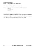
Example: SG-UTC=0,0,60 for UTC offset of 0 minutes, local reference for the DST change, and
adjustment amount of 60 minutes
The RG-DST command reports start and stop times and dates for daylight saving time referenced to local
time. Refer to Section 11,
ASCII Command Interface,
for a list of all ASCII commands.
GENERAL STATUS REPORTING
BE1-CDS240 relays have extensive capabilities for reporting relay status. This is important for
determining the health and status of the system for diagnostics and troubleshooting. Throughout this
manual, reference is made to the RG-STAT (report general, status) report and the appropriate HMI
screens for determining the status of various functions.
General Status Report
A General Status report is available through the communication ports using the RG-STAT command. This
report lists all of the information required to determine the status of the relay. An example of a typical
General Status report follows as well as a description of what each line represents. In the explanation of
each line, cross-references are made to the corresponding HMI screens that contain that data.
>RG-STAT
INPUT(1-12) STATUS : 000000000000
OUTPUT(A,1-10) STATUS : 000000000000000
CO-OUT(A,1-10) STATUS : LLLLLLLLLLLLLLL
CO-43 to CO-743 STATUS : 00000000
CO-101(101SC) STATUS : AFTER CLOSE(1)
CO-1101(1101SC) STATUS : AFTER CLOSE(1)
CO-2101(2101SC) STATUS : AFTER CLOSE(1)
CO-3101(3101SC) STATUS : AFTER CLOSE(1)
CO-GROUP STATUS : L
ACTIVE LOGIC STATUS : CDS240-BA87-A-BE
LOGIC VAR( 0- 31) STATUS : 00000000 00000000 00000000 00000000
LOGIC VAR( 32- 63) STATUS : 00000000 00000000 00000000 00000000
LOGIC VAR( 64- 95) STATUS : 00000000 00000000 00000000 00000000
LOGIC VAR( 96-127) STATUS : 00000000 00000000 00000000 00001111
LOGIC VAR(128-159) STATUS : 00000000 00000000 00000000 00000000
LOGIC VAR(160-191) STATUS : 00000000 00001000 00000000 00000000
ACTIVE GROUP STATUS : 0
BREAKER_LABEL1 STATUS : OFF
BREAKER_LABEL2 STATUS : OFF
BREAKER_LABEL3 STATUS : OFF
BREAKER_LABEL4 STATUS : OFF
DIAG/ALARM STATUS : 0 RELAY, 0 LOGIC, 0 MAJOR, 0 MINOR
Input (1-12)
This line reports the status of contact sensing inputs IN1 through IN12. Input information is available at
HMI Screen 1.4.1, \STAT\OPER\INPUT, or with the RG-INPUT ASCII command. “0” indicates a de-
energized input and “1” indicates an energized input. See Section 3,
Input and Output Functions,
for more
information about contact sensing input operation.
Output (A, 1-10)
Output contact status for OUTA, OUT1 through OUT10 is reported on this line. This information is also
available at HMI Screen 1.4.2, \STAT\OPER\OUT, or with the RG-OUTSTAT ASCII command. “0”
indicates a de-energized output and “1” indicates an energized output. More information about output
contact operation is available in Section 3,
Input and Output Functions
.
CO-OUT (A,1-10)
This line reports the logic override of the output contacts. Logic override status is reported at HMI Screen
2.4, \CTRL\OUT, and through the RG-OUTCNTRL ASCII command. Section 3,
Input and Output
Functions,
provides more information about output logic override control.
Summary of Contents for BE1-CDS240
Page 2: ......
Page 8: ...vi BE1 CDS240 Introduction 9365200990 Rev F This page intentionally left blank ...
Page 38: ...1 28 BE1 CDS240 General Information 9365200990 Rev F This page intentionally left blank ...
Page 40: ...ii BE1 CDS240 Quick Start 9365200990 Rev F This page intentionally left blank ...
Page 152: ...ii BE1 CDS240 Metering 9365200990 Rev F This page intentionally left blank ...
Page 226: ...iv BE1 CDS240 Application 9365200990 Rev F This page intentionally left blank ...
Page 286: ...ii BE1 CDS240 Security 9365200990 Rev F This page intentionally left blank ...
Page 290: ...9 4 BE1 CDS240 Security 9365200990 Rev F This page intentionally left blank ...
Page 292: ...ii BE1 CDS240 Human Machine Interface 9365200990 Rev F This page intentionally left blank ...
Page 306: ...10 14 BE1 CDS240 Human Machine Interface 9365200990 Rev F This page intentionally left blank ...
Page 308: ...ii BE1 CDS240 ASCII Command Interface 9365200990 Rev F This page intentionally left blank ...
Page 342: ...11 34 BE1 CDS240 ASCII Command Interface 9365200990 Rev F This page intentionally left blank ...
Page 349: ...Figure 12 5 Horizontal Rack Mount Front View 9365200990 Rev F BE1 CDS240 Installation 12 5 ...
Page 361: ...Figure 12 17 Typical DC Connection Diagrams 9365200990 Rev F BE1 CDS240 Installation 12 17 ...
Page 372: ...12 28 BE1 CDS240 Installation 9365200990 Rev F This page intentionally left blank ...
Page 468: ...13 92 BE1 CDS240 Testing and Maintenance 9365200990 Rev F This page intentionally left blank ...
Page 512: ...14 42 BE1 CDS240 BESTCOMS Software 9365200990 Rev F This page intentionally left blank ...
Page 544: ...ii BE1 CDS240 Terminal Communication 9365200990 Rev F This page intentionally left blank ...
Page 550: ...ii BE1 CDS240 Settings Calculations 9365200990 Rev F This page intentionally left blank ...
Page 578: ...D 28 BE1 CDS240 Settings Calculations 9365200990 Rev F This page intentionally left blank ...
Page 579: ......


