


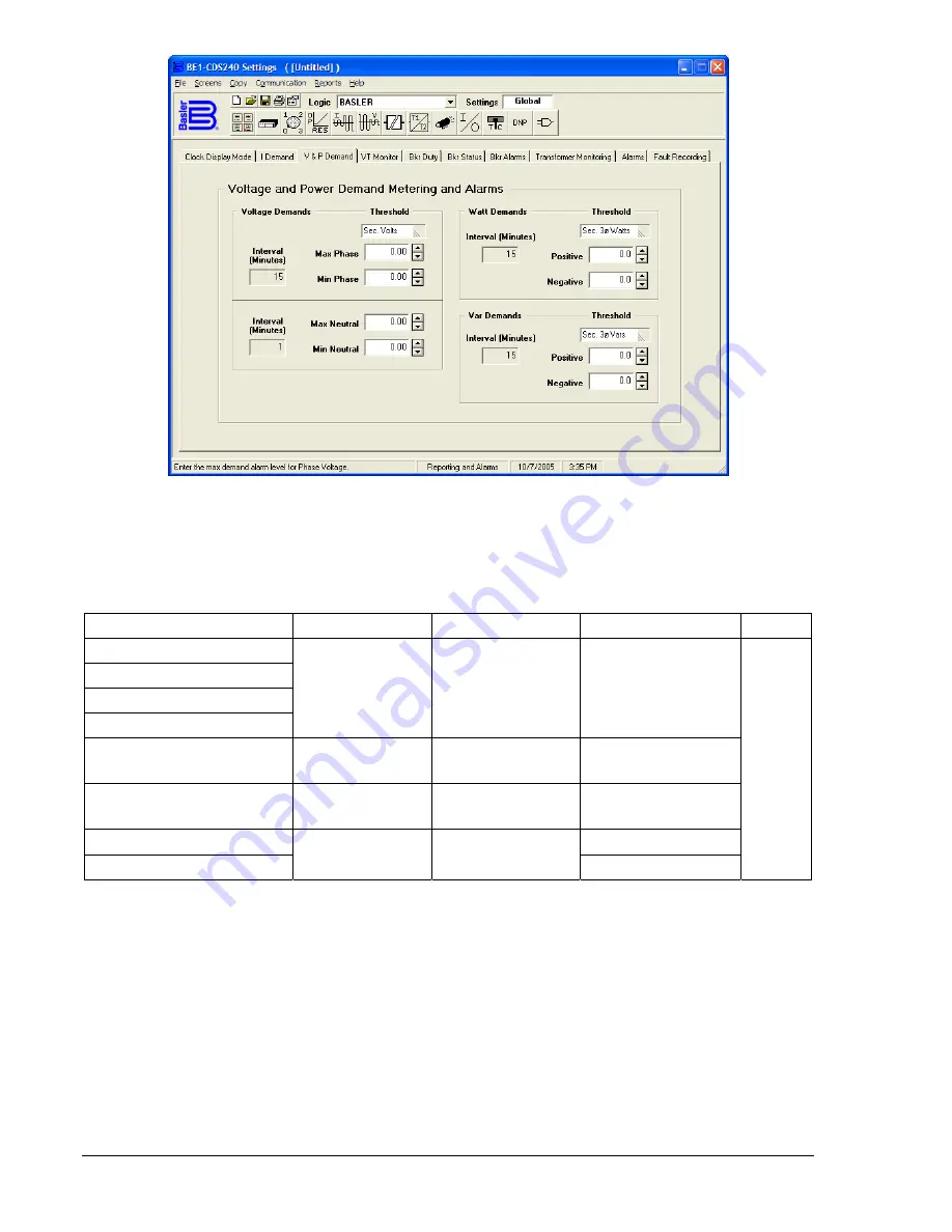
Figure 6-4. Reporting and Alarms Screen, V & P Demand Tab
Table 6-5 provides the specifications for the Demand Alarm Threshold settings. The ASCII commands for
setting the Demand Alarm Thresholds are listed in Section 11,
ASCII Command Interface.
Table 6-5. Demand Alarm Threshold Settings
Demand Alarm Threshold
Range
Increment
Unit of Measure
Default
Phase Current
Neutral Current
Neg.-Sequence Current
Ground
5A
0.50 – 16.0
1A
0.10 – 3.20
0.01 for 0 – 9.99
0.1 for 10.0 – 16.0
Secondary Amps
Voltage Max/Min Phase
10.0 – 300
0.1 for 10.0 to 99.9
1 for 100 to 300
Secondary Volts
Voltage Max/Min Neutral
10.0 - 150
0.1 for 10.0 to 99.9
1 for 100 to 150
Secondary Volts
Watts Positive/Negative
Secondary 3
Ø
Watts
Vars Positive/Negative
0 – 8500
0.1 for 0 to 99.9
1 for 100 to 8500
Secondary 3
Ø
Vars
0
Optional Load Profile Recording Function
Load profile recording is an optional selection when the BE1-CDS240 is ordered. The Load Profile, 4000
Point Data Array option (2 or 3 as the third character from the right in the style chart) uses a 4,000-point
data array for data storage. Refer to Section 1,
General Information, Model and Style Number
Description,
for more information on optional selections. At the specified (programmed) interval, Load
Profile takes the data from the demand calculation register and places it in a data array. If the
programmed interval is set to 15 minutes, it will take 41 days and 16 hours to generate 4,000 entries.
Load profile data is smoothed by the demand calculation function. If you made a step change in primary
current, with the demand interval set for fifteen minutes and the load profile recording interval set for one
minute, it would take approximately fifteen minutes for the load (step change) to reach 90 percent of the
final level. See the previous paragraphs in this section on
Demand Calculation and Reporting Function,
for information on calculation methods.
6-10
BE1-CDS240 Reporting and Alarm Functions
9365200990 Rev F
Summary of Contents for BE1-CDS240
Page 2: ......
Page 8: ...vi BE1 CDS240 Introduction 9365200990 Rev F This page intentionally left blank ...
Page 38: ...1 28 BE1 CDS240 General Information 9365200990 Rev F This page intentionally left blank ...
Page 40: ...ii BE1 CDS240 Quick Start 9365200990 Rev F This page intentionally left blank ...
Page 152: ...ii BE1 CDS240 Metering 9365200990 Rev F This page intentionally left blank ...
Page 226: ...iv BE1 CDS240 Application 9365200990 Rev F This page intentionally left blank ...
Page 286: ...ii BE1 CDS240 Security 9365200990 Rev F This page intentionally left blank ...
Page 290: ...9 4 BE1 CDS240 Security 9365200990 Rev F This page intentionally left blank ...
Page 292: ...ii BE1 CDS240 Human Machine Interface 9365200990 Rev F This page intentionally left blank ...
Page 306: ...10 14 BE1 CDS240 Human Machine Interface 9365200990 Rev F This page intentionally left blank ...
Page 308: ...ii BE1 CDS240 ASCII Command Interface 9365200990 Rev F This page intentionally left blank ...
Page 342: ...11 34 BE1 CDS240 ASCII Command Interface 9365200990 Rev F This page intentionally left blank ...
Page 349: ...Figure 12 5 Horizontal Rack Mount Front View 9365200990 Rev F BE1 CDS240 Installation 12 5 ...
Page 361: ...Figure 12 17 Typical DC Connection Diagrams 9365200990 Rev F BE1 CDS240 Installation 12 17 ...
Page 372: ...12 28 BE1 CDS240 Installation 9365200990 Rev F This page intentionally left blank ...
Page 468: ...13 92 BE1 CDS240 Testing and Maintenance 9365200990 Rev F This page intentionally left blank ...
Page 512: ...14 42 BE1 CDS240 BESTCOMS Software 9365200990 Rev F This page intentionally left blank ...
Page 544: ...ii BE1 CDS240 Terminal Communication 9365200990 Rev F This page intentionally left blank ...
Page 550: ...ii BE1 CDS240 Settings Calculations 9365200990 Rev F This page intentionally left blank ...
Page 578: ...D 28 BE1 CDS240 Settings Calculations 9365200990 Rev F This page intentionally left blank ...
Page 579: ......


