If the relay detects that the breaker is closed and no voltage is sensed across the terminals of the open
output contact after the appropriate coordination time delay (approximately 500 milliseconds), the relay
sets an alarm bit in the programmable alarms function and sets the CKTMON BESTlogic logic variable to
TRUE.
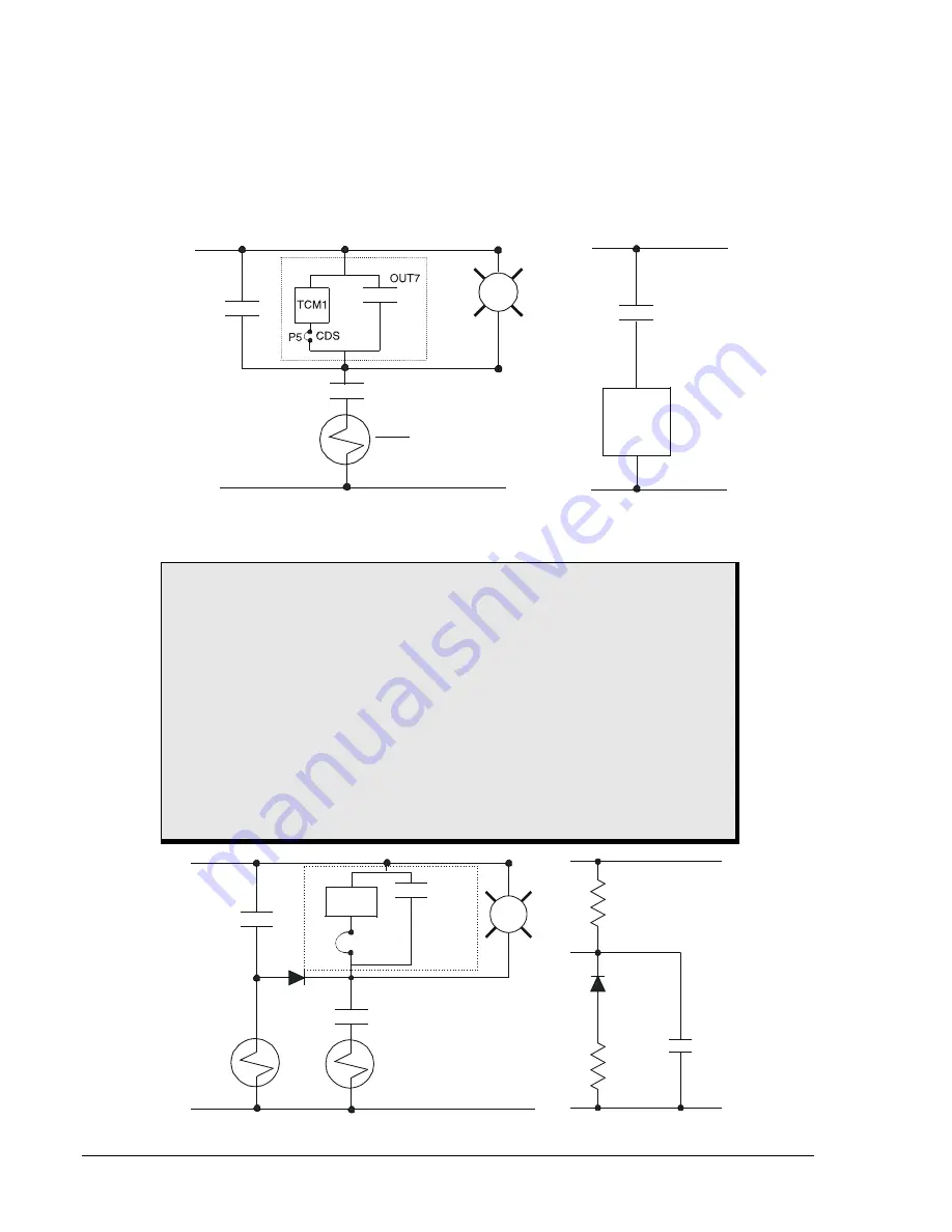
Figure 6-15 shows a typical connection diagram for the circuit monitor. Also, see Section 8,
Application,
Application Tips,
for instructions on how to program a close-circuit monitoring function in BESTlogic. In
this example, OUT7 is tripping the lockout relay (86T) and IN3 is monitoring the lockout relay status.
Trip
Other
Relays
+
-
R
86a
CDS
IN3
Status
86a
86T
TC
+
-
Trip Circuit
Relay Circuit
D2850-31
08-22-03
Figure 6-15. Trip Circuit Voltage and Continuity Monitor
CAUTION
Applications that place other device inputs in parallel with the breaker trip coil
may not perform as desired when the trip coil monitor is active. The connection of
other devices in parallel with the trip coil causes a voltage divider to occur when
the breaker or trip circuit is open. (Figure 6-16 shows a schematic representation
of the equivalent circuit.) This may cause false tripping of the other devices and
prevent the BE1-CDS240 trip circuit monitor from reliably detecting an open
circuit. If this situation exists, the trip coil monitor can be removed from the circuit.
Refer to Section 12,
Installation, Trip Coil Monitor (TCM) Jumpers,
for complete
instructions.
The circuit monitor sensing element has the same rating as the power supply
voltage. If the trip circuit voltage is significantly greater than the power supply
voltage (for example, when using a capacitor trip device), the trip circuit monitor
circuits should be disabled.
Other
Relays
+
-
TCM1
P5
CDS
OUT7
R
52a
52TC
D2850-32
08-22-03
62X
TCM
+
V
-
+
V
-
62X
52a
Trip
Figure 6-16. TCM with Other Devices
6-26
BE1-CDS240 Reporting and Alarm Functions
9365200990 Rev F
Summary of Contents for BE1-CDS240
Page 2: ......
Page 8: ...vi BE1 CDS240 Introduction 9365200990 Rev F This page intentionally left blank ...
Page 38: ...1 28 BE1 CDS240 General Information 9365200990 Rev F This page intentionally left blank ...
Page 40: ...ii BE1 CDS240 Quick Start 9365200990 Rev F This page intentionally left blank ...
Page 152: ...ii BE1 CDS240 Metering 9365200990 Rev F This page intentionally left blank ...
Page 226: ...iv BE1 CDS240 Application 9365200990 Rev F This page intentionally left blank ...
Page 286: ...ii BE1 CDS240 Security 9365200990 Rev F This page intentionally left blank ...
Page 290: ...9 4 BE1 CDS240 Security 9365200990 Rev F This page intentionally left blank ...
Page 292: ...ii BE1 CDS240 Human Machine Interface 9365200990 Rev F This page intentionally left blank ...
Page 306: ...10 14 BE1 CDS240 Human Machine Interface 9365200990 Rev F This page intentionally left blank ...
Page 308: ...ii BE1 CDS240 ASCII Command Interface 9365200990 Rev F This page intentionally left blank ...
Page 342: ...11 34 BE1 CDS240 ASCII Command Interface 9365200990 Rev F This page intentionally left blank ...
Page 349: ...Figure 12 5 Horizontal Rack Mount Front View 9365200990 Rev F BE1 CDS240 Installation 12 5 ...
Page 361: ...Figure 12 17 Typical DC Connection Diagrams 9365200990 Rev F BE1 CDS240 Installation 12 17 ...
Page 372: ...12 28 BE1 CDS240 Installation 9365200990 Rev F This page intentionally left blank ...
Page 468: ...13 92 BE1 CDS240 Testing and Maintenance 9365200990 Rev F This page intentionally left blank ...
Page 512: ...14 42 BE1 CDS240 BESTCOMS Software 9365200990 Rev F This page intentionally left blank ...
Page 544: ...ii BE1 CDS240 Terminal Communication 9365200990 Rev F This page intentionally left blank ...
Page 550: ...ii BE1 CDS240 Settings Calculations 9365200990 Rev F This page intentionally left blank ...
Page 578: ...D 28 BE1 CDS240 Settings Calculations 9365200990 Rev F This page intentionally left blank ...
Page 579: ......


