


1-10
BE1-CDS240 General Information
9365200990 Rev F
The tap adjustment factors can be used to eliminate the mismatch when the tap changer is at neutral.
But, when the tap changer is off of neutral, differential current will be measured.
BE1-CDS240 Solution
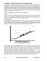
The percentage restraint characteristic of the differential function mentioned previously allows the relay to
accommodate a prescribed amount of mismatch. The differential current must exceed a percentage of the
through current as described by the slope characteristic setting of the differential protection function. Also,
the relay has four setting groups to allow the tap settings and other parameters to be changed
dynamically based upon operating conditions.
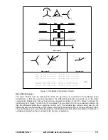
Problem 4: Phase Angle Shift
General
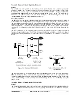
When differential protection is used in a transformer application, the transformer often introduces a phase
shift between the various current inputs to the zone of protection. An example is a transformer with a
delta- connected high side and a wye-connected low side as shown in Figure 1-4, Illustration A. The
currents in the phases connected to the delta side of the transformer are each made up of the
combination of the current flowing in two legs of the delta winding. On the other hand, the currents in the
phases connected to the wye side of the transformer are made up of the current in only one leg of the
wye winding. It can be seen that the primary currents flowing into the zone of protection when tap is
adjusted for magnitude mismatch still do not sum to zero as shown in Figure 1-4, Illustrations B and C.
Summary of Contents for BE1-CDS240
Page 2: ......
Page 8: ...vi BE1 CDS240 Introduction 9365200990 Rev F This page intentionally left blank ...
Page 38: ...1 28 BE1 CDS240 General Information 9365200990 Rev F This page intentionally left blank ...
Page 40: ...ii BE1 CDS240 Quick Start 9365200990 Rev F This page intentionally left blank ...
Page 152: ...ii BE1 CDS240 Metering 9365200990 Rev F This page intentionally left blank ...
Page 226: ...iv BE1 CDS240 Application 9365200990 Rev F This page intentionally left blank ...
Page 286: ...ii BE1 CDS240 Security 9365200990 Rev F This page intentionally left blank ...
Page 290: ...9 4 BE1 CDS240 Security 9365200990 Rev F This page intentionally left blank ...
Page 292: ...ii BE1 CDS240 Human Machine Interface 9365200990 Rev F This page intentionally left blank ...
Page 306: ...10 14 BE1 CDS240 Human Machine Interface 9365200990 Rev F This page intentionally left blank ...
Page 308: ...ii BE1 CDS240 ASCII Command Interface 9365200990 Rev F This page intentionally left blank ...
Page 342: ...11 34 BE1 CDS240 ASCII Command Interface 9365200990 Rev F This page intentionally left blank ...
Page 349: ...Figure 12 5 Horizontal Rack Mount Front View 9365200990 Rev F BE1 CDS240 Installation 12 5 ...
Page 361: ...Figure 12 17 Typical DC Connection Diagrams 9365200990 Rev F BE1 CDS240 Installation 12 17 ...
Page 372: ...12 28 BE1 CDS240 Installation 9365200990 Rev F This page intentionally left blank ...
Page 468: ...13 92 BE1 CDS240 Testing and Maintenance 9365200990 Rev F This page intentionally left blank ...
Page 512: ...14 42 BE1 CDS240 BESTCOMS Software 9365200990 Rev F This page intentionally left blank ...
Page 544: ...ii BE1 CDS240 Terminal Communication 9365200990 Rev F This page intentionally left blank ...
Page 550: ...ii BE1 CDS240 Settings Calculations 9365200990 Rev F This page intentionally left blank ...
Page 578: ...D 28 BE1 CDS240 Settings Calculations 9365200990 Rev F This page intentionally left blank ...
Page 579: ......


