


H
2
H
1
H
3
C
B
A
X
2
X
1
X
0
X
3
C
B
A
A13
A14
A9
A11
A7
A8
A5
A6
*
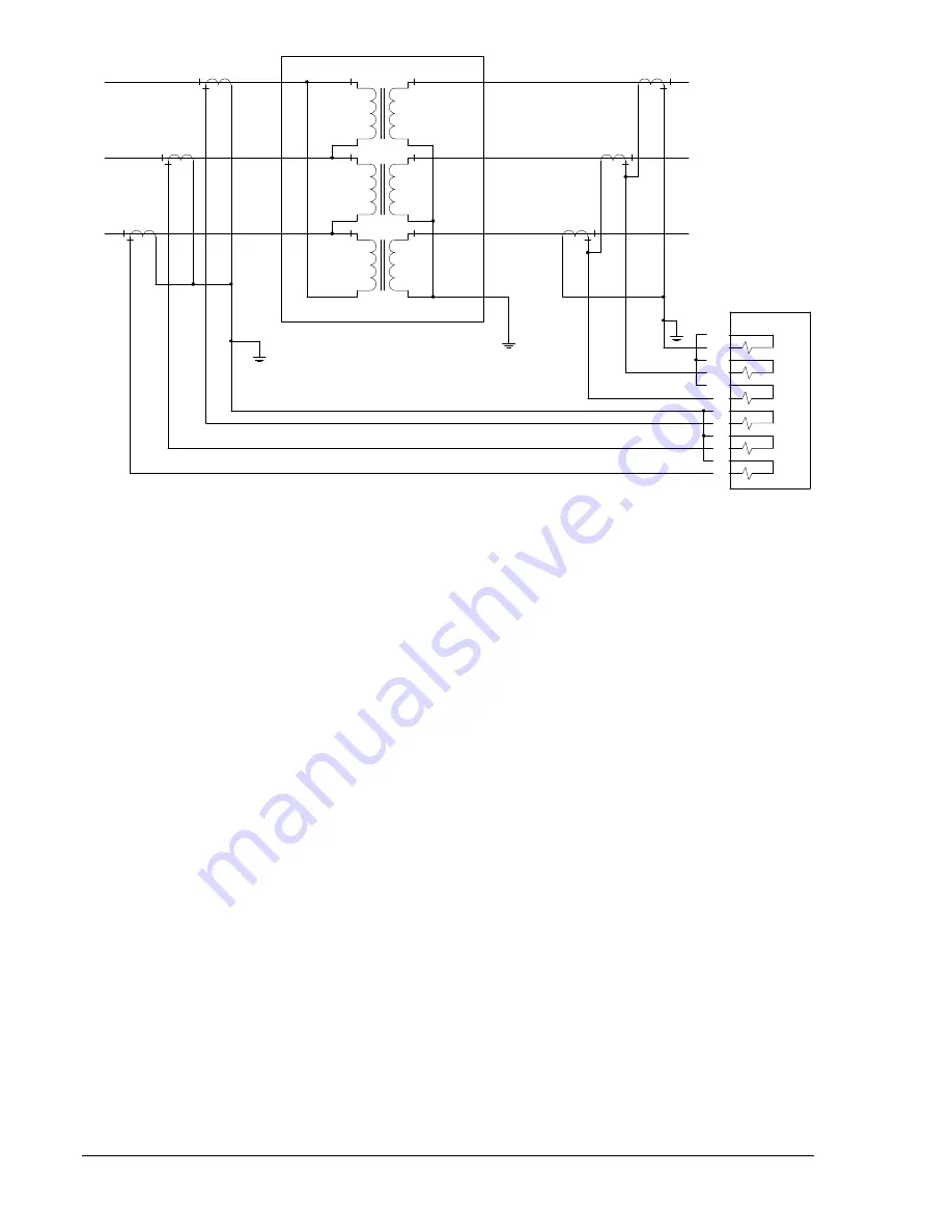
BE1-CDS240
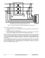
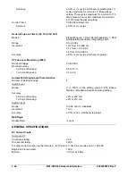
*An alternative to grounding one corner of the delta connected CTs is
to connect the ground to a lead connected to terminal A10, 12, or 14.
P0017-03
02-28-03
A4
A3
A12
A10
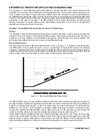
Figure 1-5. Three-Phase Connections, Delta-Wye Configuration, CT Compensation
There are several drawbacks to the traditional solution:
The delta connection requires a dedicated set of CTs that generally cannot be used for other
purposes.
The delta connection is more difficult to test.
The delta-connected CTs experience greater burden than wye-connected CTs because the lead
burden must be multiplied by a factor of three in the CT performance calculation.
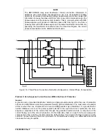
The BE1-CDS240 relays support the traditional solution so that they may be used in retrofit/modernization
projects. However, in a numerical relay, it is possible to connect all of the CTs in wye as shown in Figure
1-6 so that the drawbacks mentioned above are not a consideration. The BE1-CDS240 relay can
numerically combine currents internally to accomplish a numerical delta if required for phase angle
compensation.
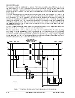
The setup parameters for each of the current input circuits are described in Section 3,
Input and Output
Functions, Power System Inputs
. The CT connection and the transformer connection are included to
allow the BE1-CDS240 relay to automatically determine the appropriate combination of currents to
present to the differential protection function.
1-12
BE1-CDS240 General Information
9365200990 Rev F
Summary of Contents for BE1-CDS240
Page 2: ......
Page 8: ...vi BE1 CDS240 Introduction 9365200990 Rev F This page intentionally left blank ...
Page 38: ...1 28 BE1 CDS240 General Information 9365200990 Rev F This page intentionally left blank ...
Page 40: ...ii BE1 CDS240 Quick Start 9365200990 Rev F This page intentionally left blank ...
Page 152: ...ii BE1 CDS240 Metering 9365200990 Rev F This page intentionally left blank ...
Page 226: ...iv BE1 CDS240 Application 9365200990 Rev F This page intentionally left blank ...
Page 286: ...ii BE1 CDS240 Security 9365200990 Rev F This page intentionally left blank ...
Page 290: ...9 4 BE1 CDS240 Security 9365200990 Rev F This page intentionally left blank ...
Page 292: ...ii BE1 CDS240 Human Machine Interface 9365200990 Rev F This page intentionally left blank ...
Page 306: ...10 14 BE1 CDS240 Human Machine Interface 9365200990 Rev F This page intentionally left blank ...
Page 308: ...ii BE1 CDS240 ASCII Command Interface 9365200990 Rev F This page intentionally left blank ...
Page 342: ...11 34 BE1 CDS240 ASCII Command Interface 9365200990 Rev F This page intentionally left blank ...
Page 349: ...Figure 12 5 Horizontal Rack Mount Front View 9365200990 Rev F BE1 CDS240 Installation 12 5 ...
Page 361: ...Figure 12 17 Typical DC Connection Diagrams 9365200990 Rev F BE1 CDS240 Installation 12 17 ...
Page 372: ...12 28 BE1 CDS240 Installation 9365200990 Rev F This page intentionally left blank ...
Page 468: ...13 92 BE1 CDS240 Testing and Maintenance 9365200990 Rev F This page intentionally left blank ...
Page 512: ...14 42 BE1 CDS240 BESTCOMS Software 9365200990 Rev F This page intentionally left blank ...
Page 544: ...ii BE1 CDS240 Terminal Communication 9365200990 Rev F This page intentionally left blank ...
Page 550: ...ii BE1 CDS240 Settings Calculations 9365200990 Rev F This page intentionally left blank ...
Page 578: ...D 28 BE1 CDS240 Settings Calculations 9365200990 Rev F This page intentionally left blank ...
Page 579: ......


