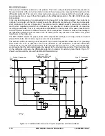


NOTE
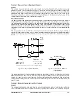
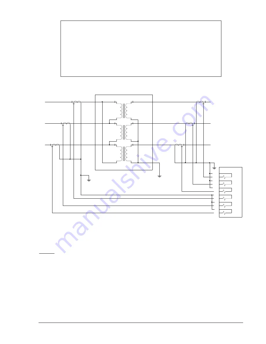
The BE1-CDS240 relay uses transformer internal connection information to
determine the correct phase compensation to use. It is not possible to reliably
determine the phase compensation settings based simply upon phase angle shift
information because the phase shift from high to low side is dependent upon the
phase-sequence of the power system phasors. That is, a power system with ABC
phase-sequence will produce a different phase shift from high to low than a
power system with ACB phase-sequence in the same transformer connection. By
specifying the transformer connections from the three-line diagram, the correct
phase compensation can be determined in all cases.
H
2
H
1
H
3
C
B
A
X
2
X
1
X
0
X
3
C
B
A
P0017-04
02-28-03
A13
A14
A9
A11
A7
A8
A5
A6
BE1-CDS240
A4
A3
A12
A10
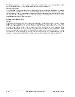
Figure 1-6. Three-Phase Connections, Delta-Wye Configuration, Internal Phase Compensation
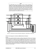
Problem 5: Zero-Sequence Current Sources Within the Zone of Protection
General
A ground source (grounded transformer winding or zigzag grounding bank) within the zone of protection
can result in differential current being measured during ground imbalances. The most common example
of this is when the zone of protection is around a delta/grounded, wye transformer. If a ground fault or
neutral imbalance occurs on the power system external to the wye side zone of protection, the zero-
sequence components of the current flow through the grounded neutral and are a component of the
current flowing out of the zone of protection. On the delta side, there is no path for the zero-sequence
components to flow and they circulate inside the delta winding. The result is that this component of the
current is not seen entering the zone of protection on the delta side resulting in a differential current that
can cause the relay to operate.
9365200990 Rev F
BE1-CDS240 General Information
1-13
Summary of Contents for BE1-CDS240
Page 2: ......
Page 8: ...vi BE1 CDS240 Introduction 9365200990 Rev F This page intentionally left blank ...
Page 38: ...1 28 BE1 CDS240 General Information 9365200990 Rev F This page intentionally left blank ...
Page 40: ...ii BE1 CDS240 Quick Start 9365200990 Rev F This page intentionally left blank ...
Page 152: ...ii BE1 CDS240 Metering 9365200990 Rev F This page intentionally left blank ...
Page 226: ...iv BE1 CDS240 Application 9365200990 Rev F This page intentionally left blank ...
Page 286: ...ii BE1 CDS240 Security 9365200990 Rev F This page intentionally left blank ...
Page 290: ...9 4 BE1 CDS240 Security 9365200990 Rev F This page intentionally left blank ...
Page 292: ...ii BE1 CDS240 Human Machine Interface 9365200990 Rev F This page intentionally left blank ...
Page 306: ...10 14 BE1 CDS240 Human Machine Interface 9365200990 Rev F This page intentionally left blank ...
Page 308: ...ii BE1 CDS240 ASCII Command Interface 9365200990 Rev F This page intentionally left blank ...
Page 342: ...11 34 BE1 CDS240 ASCII Command Interface 9365200990 Rev F This page intentionally left blank ...
Page 349: ...Figure 12 5 Horizontal Rack Mount Front View 9365200990 Rev F BE1 CDS240 Installation 12 5 ...
Page 361: ...Figure 12 17 Typical DC Connection Diagrams 9365200990 Rev F BE1 CDS240 Installation 12 17 ...
Page 372: ...12 28 BE1 CDS240 Installation 9365200990 Rev F This page intentionally left blank ...
Page 468: ...13 92 BE1 CDS240 Testing and Maintenance 9365200990 Rev F This page intentionally left blank ...
Page 512: ...14 42 BE1 CDS240 BESTCOMS Software 9365200990 Rev F This page intentionally left blank ...
Page 544: ...ii BE1 CDS240 Terminal Communication 9365200990 Rev F This page intentionally left blank ...
Page 550: ...ii BE1 CDS240 Settings Calculations 9365200990 Rev F This page intentionally left blank ...
Page 578: ...D 28 BE1 CDS240 Settings Calculations 9365200990 Rev F This page intentionally left blank ...
Page 579: ......