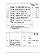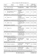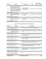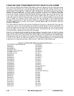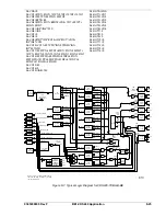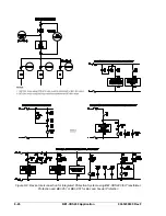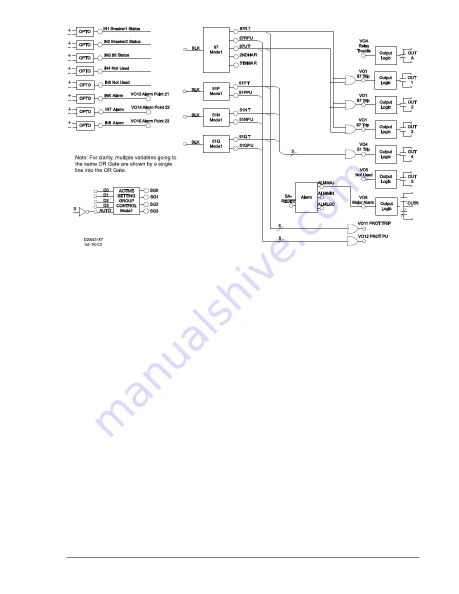
Figure 8-4. Typical Logic Diagram for CDS240-BA87-B-BE
Protection Elements
Referring to all four schemes (
G
enerator,
M
otor,
B
us, and
T
ransformer) in Figure 8-3, the 87 protection
element is connected to CT input 1 and CT input 2. The 51 protection element is also connected to the
CT input 1. The 87 and 51 protection elements are logic enabled by the programming shown in Table 8-3
to provide a trip through the BE1-CDS240 output contacts.
Typically, the 87 protection element provides high-speed percent restrained, phase and ground protection
for faults inside the differential zone. For the generator, motor, and bus applications shown in Figure 8-3,
the percent-restrained differential protection function is the only function of the 87 protection element
required. Set the pickup of the 2
nd
, 5
th
, and 87 unrestrained functions to 0 (setting disabled). The 87
restrained function has a setting when the 2
nd
and 5
th
harmonic restraint functions are set for the
transformer application shown in Figure 8-1 (refer to the discussion in
Overview Of Preprogrammed Logic
Schemes
).
Typically, the 51 protection element is coordinated with down-line protection devices to provide
overlapping Phase, Neutral, and Negative-Sequence timed backup protection for zones beyond the
equipment being protected. In the low impedance, bus application, the 51 protection element must
coordinate with the feeder protection of the circuits connected to the bus.
Integration of Protection, Control, and I/O Elements
The logic settings in Table 8-3 also include the logic equations that connect the various elements of the
basic differential scheme. For example, the three underlined commands in the equations of Table 8-7
provide the electrical connection between the 87 element (trip enabled by the settings) and trip outputs 1,
2 and 3. Referring to Figures 8-3 and 8-4, the 87 protection element trips through Outputs 1, 2, and 3.
The user can apply any or all of the outputs. The 51 protection element (also trip enabled by the settings)
trips through Output 4. There are no virtual switches used in this application.
Control of the active setting group can be manual or automatic. For the CDS240-BA87-A-BE application,
setting group control is programmed for continuous automatic operation because the /0 (not 0), logic 1 is
applied to the AUTO input of the Active Setting Group Control Logic as shown in Figure 8-4.
Alarms
Three logic variables drive the front panel LEDs: Relay Trouble (ALMREL), Major Alarm (ALMMAJ), and
Minor Alarm (ALMMIN). A fourth logic variable, Logic Alarm (ALMLGC), has no associated front panel
9365200990 Rev F
BE1-CDS240 Application
8-13
Summary of Contents for BE1-CDS240
Page 2: ......
Page 8: ...vi BE1 CDS240 Introduction 9365200990 Rev F This page intentionally left blank ...
Page 38: ...1 28 BE1 CDS240 General Information 9365200990 Rev F This page intentionally left blank ...
Page 40: ...ii BE1 CDS240 Quick Start 9365200990 Rev F This page intentionally left blank ...
Page 152: ...ii BE1 CDS240 Metering 9365200990 Rev F This page intentionally left blank ...
Page 226: ...iv BE1 CDS240 Application 9365200990 Rev F This page intentionally left blank ...
Page 286: ...ii BE1 CDS240 Security 9365200990 Rev F This page intentionally left blank ...
Page 290: ...9 4 BE1 CDS240 Security 9365200990 Rev F This page intentionally left blank ...
Page 292: ...ii BE1 CDS240 Human Machine Interface 9365200990 Rev F This page intentionally left blank ...
Page 306: ...10 14 BE1 CDS240 Human Machine Interface 9365200990 Rev F This page intentionally left blank ...
Page 308: ...ii BE1 CDS240 ASCII Command Interface 9365200990 Rev F This page intentionally left blank ...
Page 342: ...11 34 BE1 CDS240 ASCII Command Interface 9365200990 Rev F This page intentionally left blank ...
Page 349: ...Figure 12 5 Horizontal Rack Mount Front View 9365200990 Rev F BE1 CDS240 Installation 12 5 ...
Page 361: ...Figure 12 17 Typical DC Connection Diagrams 9365200990 Rev F BE1 CDS240 Installation 12 17 ...
Page 372: ...12 28 BE1 CDS240 Installation 9365200990 Rev F This page intentionally left blank ...
Page 468: ...13 92 BE1 CDS240 Testing and Maintenance 9365200990 Rev F This page intentionally left blank ...
Page 512: ...14 42 BE1 CDS240 BESTCOMS Software 9365200990 Rev F This page intentionally left blank ...
Page 544: ...ii BE1 CDS240 Terminal Communication 9365200990 Rev F This page intentionally left blank ...
Page 550: ...ii BE1 CDS240 Settings Calculations 9365200990 Rev F This page intentionally left blank ...
Page 578: ...D 28 BE1 CDS240 Settings Calculations 9365200990 Rev F This page intentionally left blank ...
Page 579: ......


