1-16
BE1-CDS240 General Information
9365200990 Rev F
These problems are more acute for differential protection since the operating quantity (differential current)
is derived from the difference between the measured quantities. Any error in magnitude or angle
measurement can result in large inaccuracies in the differential current measurement.
BE1-CDS240 Solution
Digital relay designers must decide on which of three solutions to use for this problem. They can allow
their relays to misoperate at off-nominal frequency operation. Alternatively, they can disable the
protection at off-nominal frequency. Finally, the can compensate to maintain accuracy at off-nominal
frequency. The BE1-CDS240 uses frequency tracking to adjust the sampling interval to maintain full
accuracy across a wide frequency range so that it is both secure and dependable in all applications. For
example, tripping of important transformers during a disturbance that causes the system to go unstable
can have a catastrophic affect on an already over stressed power system. Generator and motor
differential protection applications are another situation where accuracy across a wide frequency range is
important.
To eliminate the errors introduced by analog low-pass filters, the BE1-CDS240 uses digital signal
processing technology and 144 samples per cycle over-sampling to provide digital low-pass filtering.
MODEL AND STYLE NUMBER DESCRIPTION
BE1-CDS240 electrical characteristics and operating features are defined by a combination of letters and
numbers that make up the style number. The model number, together with the style number, describe the
options included in a specific device and appear in the window on the front panel and on a label located
inside the case. Upon receipt of a relay, be sure to check the style number against the requisition and the
packing list to ensure that they agree.
Sample Style Number
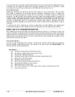
The style number identification chart of Figure 1-8 defines the electrical characteristics and operational
features included in BE1-CDS240 relays. For example, if the style number were
2B3N1H0N1A1
, the
device would have the following features.
BE1-CDS240
—
(
2
) - Two sets of three-phase current sensing circuits
(
B
) - One ampere, independent ground current sensing
(
3
) - Three-phase voltage sensing input
(
N
) - Six button human-machine interface with liquid crystal display (LCD)
(
1
) - 48/125 Vac or Vdc power supply
(
H
) - Horizontal, panel-mount case
(
0
) - ASCII communication through the RS-485 port
(
N
) - Not equipped for Ethernet communication
(
1
) - Battery backup for real-time clock
(
A
) - Ten contact outputs and 12 contact inputs. Alarm output is normally closed contact.
(
1
) - Clear front panel cover
Summary of Contents for BE1-CDS240
Page 2: ......
Page 8: ...vi BE1 CDS240 Introduction 9365200990 Rev F This page intentionally left blank ...
Page 38: ...1 28 BE1 CDS240 General Information 9365200990 Rev F This page intentionally left blank ...
Page 40: ...ii BE1 CDS240 Quick Start 9365200990 Rev F This page intentionally left blank ...
Page 152: ...ii BE1 CDS240 Metering 9365200990 Rev F This page intentionally left blank ...
Page 226: ...iv BE1 CDS240 Application 9365200990 Rev F This page intentionally left blank ...
Page 286: ...ii BE1 CDS240 Security 9365200990 Rev F This page intentionally left blank ...
Page 290: ...9 4 BE1 CDS240 Security 9365200990 Rev F This page intentionally left blank ...
Page 292: ...ii BE1 CDS240 Human Machine Interface 9365200990 Rev F This page intentionally left blank ...
Page 306: ...10 14 BE1 CDS240 Human Machine Interface 9365200990 Rev F This page intentionally left blank ...
Page 308: ...ii BE1 CDS240 ASCII Command Interface 9365200990 Rev F This page intentionally left blank ...
Page 342: ...11 34 BE1 CDS240 ASCII Command Interface 9365200990 Rev F This page intentionally left blank ...
Page 349: ...Figure 12 5 Horizontal Rack Mount Front View 9365200990 Rev F BE1 CDS240 Installation 12 5 ...
Page 361: ...Figure 12 17 Typical DC Connection Diagrams 9365200990 Rev F BE1 CDS240 Installation 12 17 ...
Page 372: ...12 28 BE1 CDS240 Installation 9365200990 Rev F This page intentionally left blank ...
Page 468: ...13 92 BE1 CDS240 Testing and Maintenance 9365200990 Rev F This page intentionally left blank ...
Page 512: ...14 42 BE1 CDS240 BESTCOMS Software 9365200990 Rev F This page intentionally left blank ...
Page 544: ...ii BE1 CDS240 Terminal Communication 9365200990 Rev F This page intentionally left blank ...
Page 550: ...ii BE1 CDS240 Settings Calculations 9365200990 Rev F This page intentionally left blank ...
Page 578: ...D 28 BE1 CDS240 Settings Calculations 9365200990 Rev F This page intentionally left blank ...
Page 579: ......


