


9365200990 Rev F
BE1-CDS240 Application
8-43
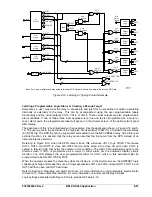
State Labels
Output Purpose
Description
Label
True False
VO9
Intermediate logic
expression for 50T and
51 Trip. Used for bus
OC trip in normal mode
or for feeder relay
backup trip in feeder
backup mode.
TRUE for any primary OC trip
(50T or 51).
50T-51-TRIP TRUE FALSE
BESTlogic Expression: VO9=50TPT+50TNT+50TQT+51PT+51NT+51QT
VO10
Intermediate logic
expression for 150T
Trip. Used for backup
bus OC trip.
TRUE for any backup
overcurrent trip (150T or 151).
150T-151-TRIP TRUE FALSE
BESTlogic Expression: VO10=151PT+151NT+151QT
VO11
Protective trip
expression.
TRUE when any 87, 50T, 150T,
51, or 151 element has timed
out.
PROTECTIVE-
TRIP
TRIP NORMAL
BESTlogic Expression: VO11=50TPT+50TNT+87RT+50TQT+51PT+151PT+51NT+
151NT+51QT+151QT
VO12
Protective pickup
expression.
TRUE when any 87, 50T, 150T,
51, or 151 element has picked
up.
PROT-
PICKED-UP
PU NORMAL
BESTlogic Expression: VO12=50TNT+87RPU+51PPU+
51QPU+151QPU
VO13
Alarm to indicate that
the differential cutoff
switch is in the block
operation position.
TRUE if Virtual Switch 43 is in
the closed position.
87-BLOCKED ACTIVE NORMAL
BESTlogic Expression: VO13=43
VO14
Alarm that relay is in
feeder backup mode.
TRUE if in setting group 1.
FDR-BU-
ENABLED
BACKUP NORMAL
BESTlogic Expression: VO14=SG1
VO15
Alarm bit #23 indication
that the relay is in test
mode and that breaker
failure is disabled.
TRUE if IN8 is de-energized or if
Virtual Switch 743 is closed.
TEST_MODE ACTIVE NORMAL
BESTlogic Expression: VO15=/IN8+743
Table 8-30. CDS240-BSBU-A-BE Hardware Output Logic
Output Purpose
Description
OUTA
Relay Trouble Alarm.
OUTA contact closes when relay trouble alarm occurs.
BESTlogic Expression: OUTA=VOA
OUT1
BUS fault trip (86B for
example).
OUT1 contact closes if restrained differential trip or for high-speed
bus OC trip (50T) and not in feeder backup mode (VO14).
BESTlogic Expression: OUT1=VO1
Summary of Contents for BE1-CDS240
Page 2: ......
Page 8: ...vi BE1 CDS240 Introduction 9365200990 Rev F This page intentionally left blank ...
Page 38: ...1 28 BE1 CDS240 General Information 9365200990 Rev F This page intentionally left blank ...
Page 40: ...ii BE1 CDS240 Quick Start 9365200990 Rev F This page intentionally left blank ...
Page 152: ...ii BE1 CDS240 Metering 9365200990 Rev F This page intentionally left blank ...
Page 226: ...iv BE1 CDS240 Application 9365200990 Rev F This page intentionally left blank ...
Page 286: ...ii BE1 CDS240 Security 9365200990 Rev F This page intentionally left blank ...
Page 290: ...9 4 BE1 CDS240 Security 9365200990 Rev F This page intentionally left blank ...
Page 292: ...ii BE1 CDS240 Human Machine Interface 9365200990 Rev F This page intentionally left blank ...
Page 306: ...10 14 BE1 CDS240 Human Machine Interface 9365200990 Rev F This page intentionally left blank ...
Page 308: ...ii BE1 CDS240 ASCII Command Interface 9365200990 Rev F This page intentionally left blank ...
Page 342: ...11 34 BE1 CDS240 ASCII Command Interface 9365200990 Rev F This page intentionally left blank ...
Page 349: ...Figure 12 5 Horizontal Rack Mount Front View 9365200990 Rev F BE1 CDS240 Installation 12 5 ...
Page 361: ...Figure 12 17 Typical DC Connection Diagrams 9365200990 Rev F BE1 CDS240 Installation 12 17 ...
Page 372: ...12 28 BE1 CDS240 Installation 9365200990 Rev F This page intentionally left blank ...
Page 468: ...13 92 BE1 CDS240 Testing and Maintenance 9365200990 Rev F This page intentionally left blank ...
Page 512: ...14 42 BE1 CDS240 BESTCOMS Software 9365200990 Rev F This page intentionally left blank ...
Page 544: ...ii BE1 CDS240 Terminal Communication 9365200990 Rev F This page intentionally left blank ...
Page 550: ...ii BE1 CDS240 Settings Calculations 9365200990 Rev F This page intentionally left blank ...
Page 578: ...D 28 BE1 CDS240 Settings Calculations 9365200990 Rev F This page intentionally left blank ...
Page 579: ......


