Close-Circuit Monitor
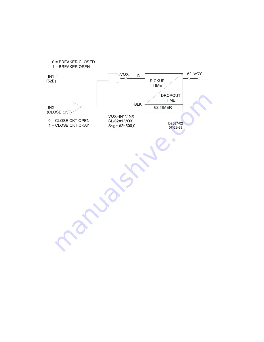
A close-circuit monitor is not included in any of the preprogrammed logic schemes. This function may be
added by using a 62 function block and a contact sensing input (INX) to monitor the close circuit. The
logic is shown in Figure 8-16. The output of the 62 protection block will close the designated output
contact (VOY) when an open breaker and an open close-circuit condition exist. The S<g>-62 command is
used to provide a 500-millisecond time delay to inhibit the momentary alarm that will occur due to the
timing difference between the two signals.
Figure 8-16. Close Circuit Monitor Logic
Block Neutral and Negative Sequence Protection
The neutral and negative sequence overcurrent elements provide greater sensitivity to unbalanced faults
than the phase overcurrent elements because they can be set to pickup below balanced three-phase
load. This can lead to a misoperation during periods of load imbalance. The BE1-CDS240 provides a
neutral and negative sequence demand function that allows monitoring and alarming to prevent load
imbalances. However, distribution systems with single-pole fault clearing and switching devices or long
single-phase laterals, may have misoperation during switching activities.
Some of the preprogrammed logic schemes provide for the use of a cutoff switch to block the ground and
negative sequence 50T (used for low set instantaneous) and the 51 (inverse time) function blocks during
switching activities. This is the most conservative approach. The protection engineer may wish to
evaluate this strategy based on his system, his/her operating practices, and his/her setting practices. For
instance, on systems with wye-connected loads, the ground units are most sensitive to this situation. On
systems with delta connected loads the negative sequence units are most sensitive to this situation. It
may not be necessary to block the instantaneous units if their settings prevent them from tripping for a
switching imbalance.
To maintain proper coordination, the logic of the feeder relays may be interconnected with the upstream
bus relay to block the equivalent ground and/or negative sequence function blocks in the upstream relay.
Setting Group Selection
The BE1-CDS240 Current Differential System provides multiple settings groups for adaptive relaying. The
preprogrammed logic schemes barely demonstrate the flexibility available. The following examples
illustrate how the setting groups can be adapted for different conditions and how different setting groups
can be used to vary the system logic.
Example 1:
Adapting the relay settings for different conditions.
In overcurrent protection systems, the source conditions can have a major impact on sensitivity,
coordination intervals, and clearing times. Generally, the pickup and time dial settings are a compromise
between a normal condition and a worst-case condition. Contact logic from the position of the source
breakers can select which settings group is active. To do this, assign input D0 or D1 to a contact sensing
input. Set the setting group selection mode at 2 for binary coded selection. If D0 is set, group 0 will be
selected when the input is off (binary code 00). Group 1 will be selected when the input is on (binary code
01). Similarly, if D1 is set, group 2 will be selected when the input is on (binary coded 10).
8-54
BE1-CDS240 Application
9365200990 Rev F
Summary of Contents for BE1-CDS240
Page 2: ......
Page 8: ...vi BE1 CDS240 Introduction 9365200990 Rev F This page intentionally left blank ...
Page 38: ...1 28 BE1 CDS240 General Information 9365200990 Rev F This page intentionally left blank ...
Page 40: ...ii BE1 CDS240 Quick Start 9365200990 Rev F This page intentionally left blank ...
Page 152: ...ii BE1 CDS240 Metering 9365200990 Rev F This page intentionally left blank ...
Page 226: ...iv BE1 CDS240 Application 9365200990 Rev F This page intentionally left blank ...
Page 286: ...ii BE1 CDS240 Security 9365200990 Rev F This page intentionally left blank ...
Page 290: ...9 4 BE1 CDS240 Security 9365200990 Rev F This page intentionally left blank ...
Page 292: ...ii BE1 CDS240 Human Machine Interface 9365200990 Rev F This page intentionally left blank ...
Page 306: ...10 14 BE1 CDS240 Human Machine Interface 9365200990 Rev F This page intentionally left blank ...
Page 308: ...ii BE1 CDS240 ASCII Command Interface 9365200990 Rev F This page intentionally left blank ...
Page 342: ...11 34 BE1 CDS240 ASCII Command Interface 9365200990 Rev F This page intentionally left blank ...
Page 349: ...Figure 12 5 Horizontal Rack Mount Front View 9365200990 Rev F BE1 CDS240 Installation 12 5 ...
Page 361: ...Figure 12 17 Typical DC Connection Diagrams 9365200990 Rev F BE1 CDS240 Installation 12 17 ...
Page 372: ...12 28 BE1 CDS240 Installation 9365200990 Rev F This page intentionally left blank ...
Page 468: ...13 92 BE1 CDS240 Testing and Maintenance 9365200990 Rev F This page intentionally left blank ...
Page 512: ...14 42 BE1 CDS240 BESTCOMS Software 9365200990 Rev F This page intentionally left blank ...
Page 544: ...ii BE1 CDS240 Terminal Communication 9365200990 Rev F This page intentionally left blank ...
Page 550: ...ii BE1 CDS240 Settings Calculations 9365200990 Rev F This page intentionally left blank ...
Page 578: ...D 28 BE1 CDS240 Settings Calculations 9365200990 Rev F This page intentionally left blank ...
Page 579: ......


