Table 8-38. Output Contact Seal-in Logic
Command Purpose
SG-HOLD1=0
Turn off the hold timer for output 1.
SL-62=1,IN1,0
Set the timer logic to mode 1 (pickup/dropout), IN1 to initiate, no blocking.
S#-62=2c,2c
Set the pickup (2 cycles) and dropout (2 cycles) times.
VO1=87RT+87UT+VO1
/62
Set the tripping logic for restrained 87 or unrestrained 87 or Virtual Output 1 and
not 62.
VO2=87RT+87UT+VO7
Set the closing logic for restrained 87 or unrestrained 87 or Virtual Output 7.
VO6=VO1
/62
Set the Virtual Output 6 logic to VO1 and not 62.
VO7=VO2
62
Set the Virtual Output 7 logic to VO2 and 62.
E Exit.
Y Save
settings.
Latching a Tripping Contact
On occasion, an application will call for latching an output contact. As an example, assume that a BE1-
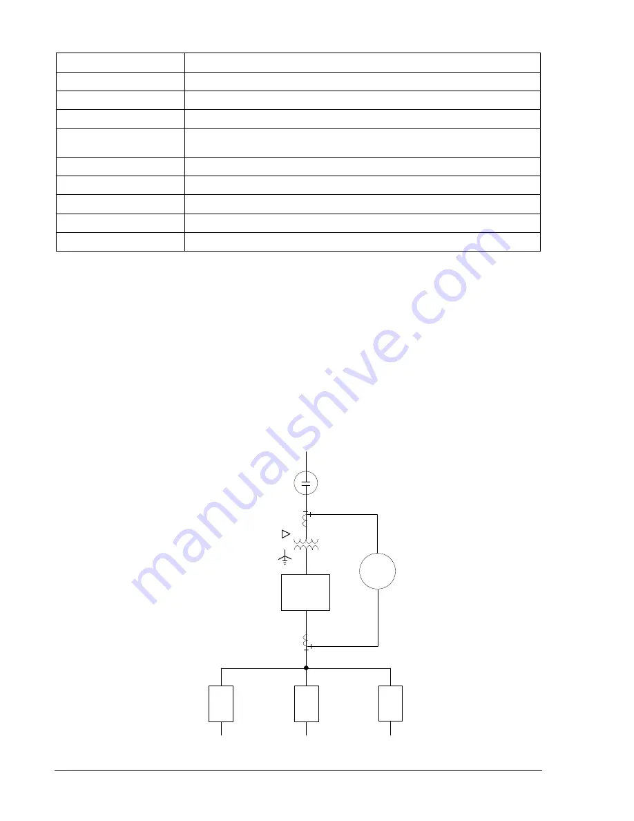
CDS240 is used for protection of a radial transformer as shown in Figure 8-18. The user wants to trip and
lockout the high-side circuit switcher for a differential trip but not for an overcurrent trip. He/she does not
want the transformer to be re-energized until someone locally checks and resets the relay.
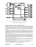
Referring to Figure 8-19, which is an adaptation of CDS240-BA87-B-BE logic, an 87 trip will cause VO7 to
go TRUE. This causes OUT1, OUT2, and OUT3 to close and OUT5 that would be wired in the close
circuit, to open. VO7 is sealed in via VO8 and holds the outputs in this condition. The optional front panel
HMI LCD automatically goes to the
Targets
screen per the automatic display priority function. When the
operator presses the
Reset
key while the display is on the
Targets
screen, the TRSTKEY logic variable
goes high and breaks the seal-in of logic expressions VO7 and VO8. Outputs OUT1, OUT2, and OUT3
will then open and OUT5 will close.
P0004-44
02-26-03
52
52
52
52
BUS
MAIN
CSW
BE1-
CDS240
Figure 8-18. Station One-line Drawing
8-56
BE1-CDS240 Application
9365200990 Rev F
Summary of Contents for BE1-CDS240
Page 2: ......
Page 8: ...vi BE1 CDS240 Introduction 9365200990 Rev F This page intentionally left blank ...
Page 38: ...1 28 BE1 CDS240 General Information 9365200990 Rev F This page intentionally left blank ...
Page 40: ...ii BE1 CDS240 Quick Start 9365200990 Rev F This page intentionally left blank ...
Page 152: ...ii BE1 CDS240 Metering 9365200990 Rev F This page intentionally left blank ...
Page 226: ...iv BE1 CDS240 Application 9365200990 Rev F This page intentionally left blank ...
Page 286: ...ii BE1 CDS240 Security 9365200990 Rev F This page intentionally left blank ...
Page 290: ...9 4 BE1 CDS240 Security 9365200990 Rev F This page intentionally left blank ...
Page 292: ...ii BE1 CDS240 Human Machine Interface 9365200990 Rev F This page intentionally left blank ...
Page 306: ...10 14 BE1 CDS240 Human Machine Interface 9365200990 Rev F This page intentionally left blank ...
Page 308: ...ii BE1 CDS240 ASCII Command Interface 9365200990 Rev F This page intentionally left blank ...
Page 342: ...11 34 BE1 CDS240 ASCII Command Interface 9365200990 Rev F This page intentionally left blank ...
Page 349: ...Figure 12 5 Horizontal Rack Mount Front View 9365200990 Rev F BE1 CDS240 Installation 12 5 ...
Page 361: ...Figure 12 17 Typical DC Connection Diagrams 9365200990 Rev F BE1 CDS240 Installation 12 17 ...
Page 372: ...12 28 BE1 CDS240 Installation 9365200990 Rev F This page intentionally left blank ...
Page 468: ...13 92 BE1 CDS240 Testing and Maintenance 9365200990 Rev F This page intentionally left blank ...
Page 512: ...14 42 BE1 CDS240 BESTCOMS Software 9365200990 Rev F This page intentionally left blank ...
Page 544: ...ii BE1 CDS240 Terminal Communication 9365200990 Rev F This page intentionally left blank ...
Page 550: ...ii BE1 CDS240 Settings Calculations 9365200990 Rev F This page intentionally left blank ...
Page 578: ...D 28 BE1 CDS240 Settings Calculations 9365200990 Rev F This page intentionally left blank ...
Page 579: ......


