


87
Mode1
87RT
87RPU
IN4 63_SPR
OPTO
P0004-08
08-22-00
BLK
5
Note: For clarity, multiple variables going to the same OR Gate are shown by a single line into the OR Gate.
87UT
2NDHAR
5THHAR
51P
Mode1
51PT
51PPU
51N
Mode1
51NT
51NPU
51Q
Mode1
51QT
51QPU
BLK
BLK
BLK
5
VO11 PROT TRIP
VO12 PROT PU
VOA
Relay
Trouble
OUTA
Output
Logic
VO1
87 Trip
OUT1
Output
Logic
VO2
87 Trip
OUT2
Output
Logic
HMI
TRSTKEY
ARSTKEY
VO3
87 Trip
OUT3
Output
Logic
VO4
51 Trip
OUT4
Output
Logic
OUT5
Output
Logic
VO5
Block Close
3
VO7
87 Trip
VO8
87_Seal-In
VO9
SPR_Seal-In
VO13
SPR_Trip
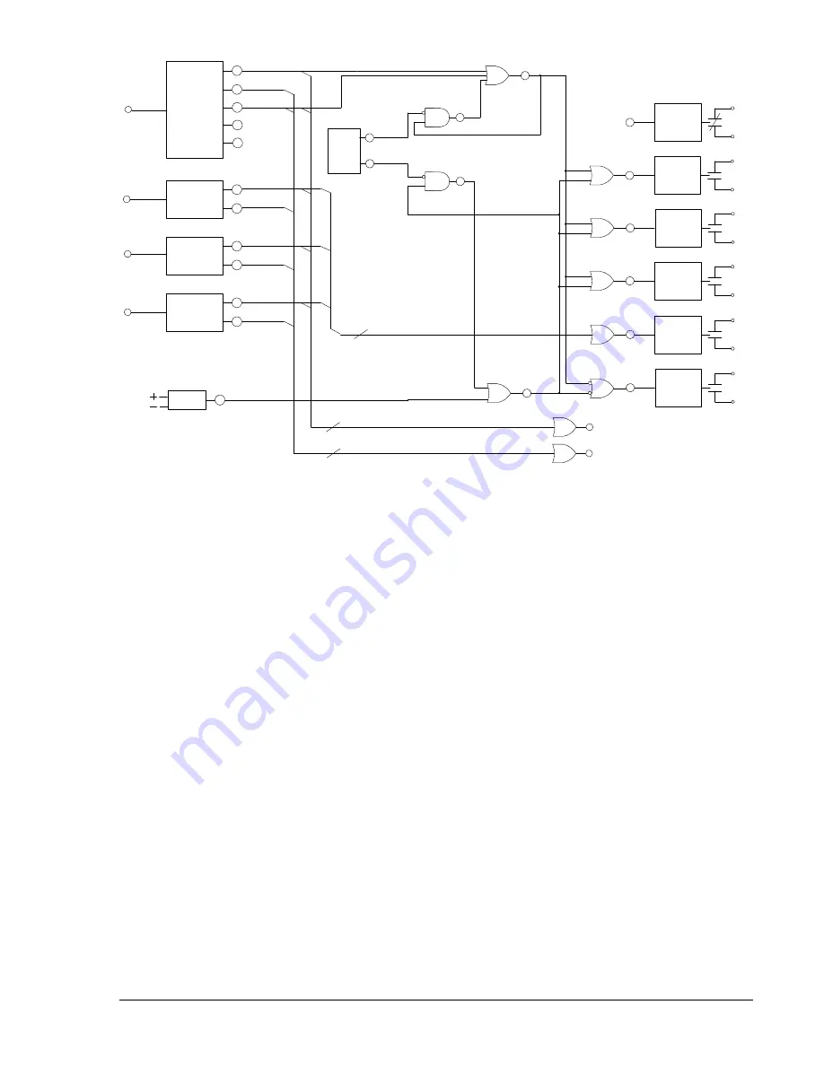
Figure 8-19. Latching a Tripping Contact Example
Latching a Programmable Logic Alarm or Creating a Pseudo Target
Sometimes, a user may want the relay to annunciate and latch for a user-defined condition originating
internally or externally to the relay. This can be accomplished using the user programmable labels
functionality and the virtual outputs VO13, VO14, or VO15. These virtual outputs are also programmable
alarm variables. If one of these three logic expressions is true and is also programmed as a major or
minor alarm point, the programmable label will appear on the
Alarms
screen of the optional front panel
HMI display.
The application of this is best illustrated with an example. Use the application shown in Figure 8-18 and 8-
19. The user wants to trip and lockout the high side circuit switcher (CSW) for a Sudden Pressure Relay
(63_SPR) trip. The SPR trip is to be supervised and sealed in via the BE1-CDS240 relay. Since this is an
external function, it is desired that the relay annunciate that the trip came from the SPR instead of an
internal protective element.
Referring to Figure 8-19, when the SPR contact closes, IN4 will cause VO13 to go TRUE. This causes
OUT1, OUT2, and OUT3 to close and OUT5 that would be wired in the close circuit to open. VO13 is
sealed in through VO9 that holds the outputs in this condition. The HMI LCD automatically goes to the
Alarms
screen if VO13 is programmed as a major or minor alarm per the automatic display priority
function. The LCD displays the user programmable label for VO13 which in this example might be
programmed to be SN-VO13=SPR_TRIP.
When the operator presses the
Reset
key while the display is on the
Alarms
screen, the ARSTKEY logic
variable goes high and breaks the seal in of logic expressions VO13 and VO9. Outputs OUT1, OUT2, and
OUT3 will then open and OUT5 will close.
Refer to Section 6,
Reporting and Alarm Functions,
for more information on programmable alarms. Refer
to Section 10,
Human Machine Interface,
for more information on Automatic Display Priorities.
Logic settings associated with Figure 8-19 are provided in Table 8-19.
9365200990 Rev F
BE1-CDS240 Application
8-57
Summary of Contents for BE1-CDS240
Page 2: ......
Page 8: ...vi BE1 CDS240 Introduction 9365200990 Rev F This page intentionally left blank ...
Page 38: ...1 28 BE1 CDS240 General Information 9365200990 Rev F This page intentionally left blank ...
Page 40: ...ii BE1 CDS240 Quick Start 9365200990 Rev F This page intentionally left blank ...
Page 152: ...ii BE1 CDS240 Metering 9365200990 Rev F This page intentionally left blank ...
Page 226: ...iv BE1 CDS240 Application 9365200990 Rev F This page intentionally left blank ...
Page 286: ...ii BE1 CDS240 Security 9365200990 Rev F This page intentionally left blank ...
Page 290: ...9 4 BE1 CDS240 Security 9365200990 Rev F This page intentionally left blank ...
Page 292: ...ii BE1 CDS240 Human Machine Interface 9365200990 Rev F This page intentionally left blank ...
Page 306: ...10 14 BE1 CDS240 Human Machine Interface 9365200990 Rev F This page intentionally left blank ...
Page 308: ...ii BE1 CDS240 ASCII Command Interface 9365200990 Rev F This page intentionally left blank ...
Page 342: ...11 34 BE1 CDS240 ASCII Command Interface 9365200990 Rev F This page intentionally left blank ...
Page 349: ...Figure 12 5 Horizontal Rack Mount Front View 9365200990 Rev F BE1 CDS240 Installation 12 5 ...
Page 361: ...Figure 12 17 Typical DC Connection Diagrams 9365200990 Rev F BE1 CDS240 Installation 12 17 ...
Page 372: ...12 28 BE1 CDS240 Installation 9365200990 Rev F This page intentionally left blank ...
Page 468: ...13 92 BE1 CDS240 Testing and Maintenance 9365200990 Rev F This page intentionally left blank ...
Page 512: ...14 42 BE1 CDS240 BESTCOMS Software 9365200990 Rev F This page intentionally left blank ...
Page 544: ...ii BE1 CDS240 Terminal Communication 9365200990 Rev F This page intentionally left blank ...
Page 550: ...ii BE1 CDS240 Settings Calculations 9365200990 Rev F This page intentionally left blank ...
Page 578: ...D 28 BE1 CDS240 Settings Calculations 9365200990 Rev F This page intentionally left blank ...
Page 579: ......