


CT Polarity
CT polarity is critical to the proper operation of the BE1-CDS240. The sidebar below provides
fundamental information on CT polarity and protective relays.
Sidebar: Current Circuit Polarity
By ANSI convention, Current Transformer Polarity will face away from the protected winding of a
transformer, motor, generator or reactor and away from the contacts in a circuit breaker. Therefore,
primary current flow towards the winding or contacts (direction of protected zone) will result in a
secondary current out X1, in phase with the primary. (See Figures 12-18 and 12-19.)
D2877-06
07-17-00
Figure 12-18. Standard CT Polarity
Figure 12-19. Current Transformer Action
On occasion, however, protection engineers will encounter situations where CT polarity is reversed for
a specific application. That is, non-polarity of the CT secondary will be in phase with the primary
current flow (Figure 12-20). For example, a transformer differential CT from a breaker with a different
polarity convention, such as low voltage switchgear or a bus differential CT taken from the low side of a
transformer.
Figure 12-20. Example of Reversed CT Polarity
Orientation of CT polarity relative to primary current flow establishes the secondary CT terminal that
should be connected to polarity of the protective relay.
12-18
BE1-CDS240 Installation
9365200990 Rev F
Summary of Contents for BE1-CDS240
Page 2: ......
Page 8: ...vi BE1 CDS240 Introduction 9365200990 Rev F This page intentionally left blank ...
Page 38: ...1 28 BE1 CDS240 General Information 9365200990 Rev F This page intentionally left blank ...
Page 40: ...ii BE1 CDS240 Quick Start 9365200990 Rev F This page intentionally left blank ...
Page 152: ...ii BE1 CDS240 Metering 9365200990 Rev F This page intentionally left blank ...
Page 226: ...iv BE1 CDS240 Application 9365200990 Rev F This page intentionally left blank ...
Page 286: ...ii BE1 CDS240 Security 9365200990 Rev F This page intentionally left blank ...
Page 290: ...9 4 BE1 CDS240 Security 9365200990 Rev F This page intentionally left blank ...
Page 292: ...ii BE1 CDS240 Human Machine Interface 9365200990 Rev F This page intentionally left blank ...
Page 306: ...10 14 BE1 CDS240 Human Machine Interface 9365200990 Rev F This page intentionally left blank ...
Page 308: ...ii BE1 CDS240 ASCII Command Interface 9365200990 Rev F This page intentionally left blank ...
Page 342: ...11 34 BE1 CDS240 ASCII Command Interface 9365200990 Rev F This page intentionally left blank ...
Page 349: ...Figure 12 5 Horizontal Rack Mount Front View 9365200990 Rev F BE1 CDS240 Installation 12 5 ...
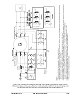
Page 361: ...Figure 12 17 Typical DC Connection Diagrams 9365200990 Rev F BE1 CDS240 Installation 12 17 ...
Page 372: ...12 28 BE1 CDS240 Installation 9365200990 Rev F This page intentionally left blank ...
Page 468: ...13 92 BE1 CDS240 Testing and Maintenance 9365200990 Rev F This page intentionally left blank ...
Page 512: ...14 42 BE1 CDS240 BESTCOMS Software 9365200990 Rev F This page intentionally left blank ...
Page 544: ...ii BE1 CDS240 Terminal Communication 9365200990 Rev F This page intentionally left blank ...
Page 550: ...ii BE1 CDS240 Settings Calculations 9365200990 Rev F This page intentionally left blank ...
Page 578: ...D 28 BE1 CDS240 Settings Calculations 9365200990 Rev F This page intentionally left blank ...
Page 579: ......


