


12-24
BE1-CDS240 Installation
9365200990 Rev F
SETTINGS
Settings for your application should be entered and confirmed before placing the relay in service. Register
settings such as breaker operations and breaker duty can be entered to match the current state of your
system.
PREPARING THE RELAY FOR SERVICE
Basler microprocessor-based protection systems are similar in nature to a panel of electromechanical or
solid-state component relays. Both must be wired together with inputs, outputs, and have operating
settings applied. Logic settings determine which protection elements are electronically wired to the inputs
and outputs of the device. Operating settings determine the pickup thresholds and time delays. The logic
and operating settings should be tested by applying actual inputs and operating quantities and verifying
proper output response. For more details, refer to Section 13,
Testing and Maintenance.
All of the
following connections and functions should be verified during commissioning tests:
•
Proper connection and sensing of current and voltage signals
•
Input and output contact connections
•
I/O sensing versus virtual sensing
• Settings
validation
•
Proper operation of equipment (main or auxiliary)
•
Proper alarming (to SCADA) and/or targeting
Refer to Section 7,
BESTlogic Programmable Logic,
for information about customizing preprogrammed
logic and creating user-defined logic and Section 8,
Application,
for information about the application of
preprogrammed logic schemes.
COMMUNICATIONS CONNECTIONS
The following paragraphs describe the communication connections for the BE1-CDS240. Section 11,
ASCII Command Interface,
provides information about using the relay communication interface and lists
all communication commands along with a description and the syntax for each command.
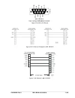
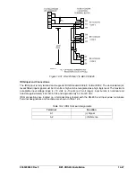
RS-232 Connectors
Front and rear panel RS-232 connectors are Data Communication Equipment (DCE) DB-9 female
connectors. Connector pin numbers, functions, names, and signal directions are shown in Table 12-2 and
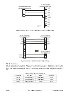
Figure 12-26. RS-232 cable connection diagrams are provided in Figures 12-27 through 12-30. Optional
Clear to Send (CTS) and Request to Send (RTS) connections are required only if hardware handshaking
is enabled.
Table 12-2. RS-232 Pinouts (COM0 and COM1)
Name Function Name Direction
1 Shield ---- N/A
2
Transmit Data
(TXD)
From relay
3
Receive Data
(RXD)
Into relay
4 N/C ---- N/A
5 Signal
Ground
(GND)
N/A
6 N/C ---- N/A
7 N/C ---- N/A
8 N/C ---- N/A
9 N/C ---- N/A
Summary of Contents for BE1-CDS240
Page 2: ......
Page 8: ...vi BE1 CDS240 Introduction 9365200990 Rev F This page intentionally left blank ...
Page 38: ...1 28 BE1 CDS240 General Information 9365200990 Rev F This page intentionally left blank ...
Page 40: ...ii BE1 CDS240 Quick Start 9365200990 Rev F This page intentionally left blank ...
Page 152: ...ii BE1 CDS240 Metering 9365200990 Rev F This page intentionally left blank ...
Page 226: ...iv BE1 CDS240 Application 9365200990 Rev F This page intentionally left blank ...
Page 286: ...ii BE1 CDS240 Security 9365200990 Rev F This page intentionally left blank ...
Page 290: ...9 4 BE1 CDS240 Security 9365200990 Rev F This page intentionally left blank ...
Page 292: ...ii BE1 CDS240 Human Machine Interface 9365200990 Rev F This page intentionally left blank ...
Page 306: ...10 14 BE1 CDS240 Human Machine Interface 9365200990 Rev F This page intentionally left blank ...
Page 308: ...ii BE1 CDS240 ASCII Command Interface 9365200990 Rev F This page intentionally left blank ...
Page 342: ...11 34 BE1 CDS240 ASCII Command Interface 9365200990 Rev F This page intentionally left blank ...
Page 349: ...Figure 12 5 Horizontal Rack Mount Front View 9365200990 Rev F BE1 CDS240 Installation 12 5 ...
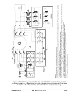
Page 361: ...Figure 12 17 Typical DC Connection Diagrams 9365200990 Rev F BE1 CDS240 Installation 12 17 ...
Page 372: ...12 28 BE1 CDS240 Installation 9365200990 Rev F This page intentionally left blank ...
Page 468: ...13 92 BE1 CDS240 Testing and Maintenance 9365200990 Rev F This page intentionally left blank ...
Page 512: ...14 42 BE1 CDS240 BESTCOMS Software 9365200990 Rev F This page intentionally left blank ...
Page 544: ...ii BE1 CDS240 Terminal Communication 9365200990 Rev F This page intentionally left blank ...
Page 550: ...ii BE1 CDS240 Settings Calculations 9365200990 Rev F This page intentionally left blank ...
Page 578: ...D 28 BE1 CDS240 Settings Calculations 9365200990 Rev F This page intentionally left blank ...
Page 579: ......


