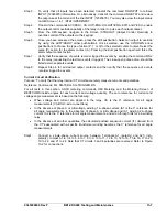
Sidebar 13-1. Testing with Internal Phase and I0 Compensation
When the internal phase and zero-sequence compensation feature of the BE1-CDS240 is used,
confusing test results can occur unless the compensation is taken into consideration. The best way to
illustrate how the BE1-CDS240 relay performs internal phase compensation and thus, what to expect
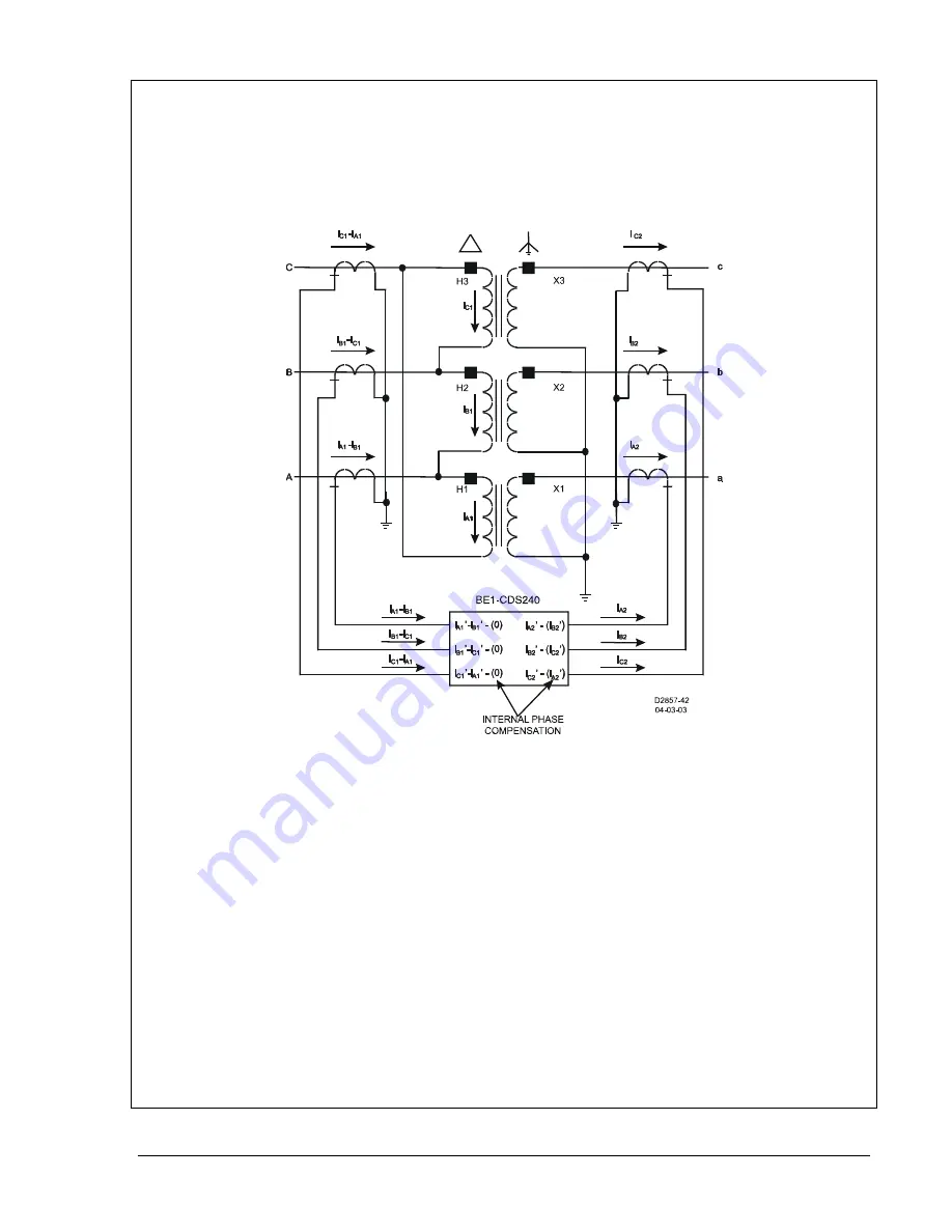
under test situations, is by looking at an application example. The application below shows a
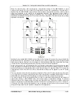
delta/grounded-wye transformer with wye connected CTs. The currents flowing into and out of the
transformer and reflected through the CTs are shown for this configuration. This test shows a two winding
application for simplicity.
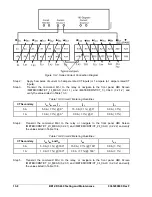
Isolating the box marked BE1-CDS240, we see that, for the A phase 87 element, the relay subtracts the
measured Ib from the measured Ia on the transformer wye side to compensate for the measured IA-IB
delta currents that are flowing in the line phases on the transformer delta side. Remember that these
currents are the compensating currents when the relay is in service for this application.
Under a test scenario, any set of balanced, 180
out of phase, single-phase, input currents that we apply
to the two phase A connections will result in balanced currents in the 87A element. However, the 87C
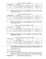
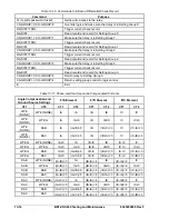
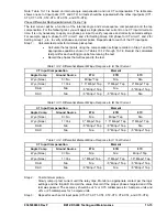
element will also see a compensating -IA2 current that will cause it to operate. Table 13-11 shows the
compensated currents that with the various compensation settings will be applied to each 87 phase
element.
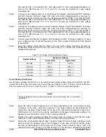
The relay can also remove the zero-sequence component of the current if a zero-sequence source exists
on an input that is not delta compensated. When this compensation is applied during testing, it has a
similar effect as subtracting I0 from the phases not under test. This also causes them to operate.
You must be aware of this compensating effect in order to understand what operations and targets to
expect when testing a BE1-CDS240 relay with internal phase compensation settings. To prevent
unwanted phases from tripping during the slope test that starts from a balanced condition, delta test
injection connections are recommended as shown in Table 13-11 and Figures 13-4 to 13-11. Tables 13-
12 through 13-14 also show what equation to use to calculate the test points for the minimum pickup
(minpu) and slope tests for each possible configuration of compensation.
9365200990 Rev F
BE1-CDS240 Testing and Maintenance
13-13
Summary of Contents for BE1-CDS240
Page 2: ......
Page 8: ...vi BE1 CDS240 Introduction 9365200990 Rev F This page intentionally left blank ...
Page 38: ...1 28 BE1 CDS240 General Information 9365200990 Rev F This page intentionally left blank ...
Page 40: ...ii BE1 CDS240 Quick Start 9365200990 Rev F This page intentionally left blank ...
Page 152: ...ii BE1 CDS240 Metering 9365200990 Rev F This page intentionally left blank ...
Page 226: ...iv BE1 CDS240 Application 9365200990 Rev F This page intentionally left blank ...
Page 286: ...ii BE1 CDS240 Security 9365200990 Rev F This page intentionally left blank ...
Page 290: ...9 4 BE1 CDS240 Security 9365200990 Rev F This page intentionally left blank ...
Page 292: ...ii BE1 CDS240 Human Machine Interface 9365200990 Rev F This page intentionally left blank ...
Page 306: ...10 14 BE1 CDS240 Human Machine Interface 9365200990 Rev F This page intentionally left blank ...
Page 308: ...ii BE1 CDS240 ASCII Command Interface 9365200990 Rev F This page intentionally left blank ...
Page 342: ...11 34 BE1 CDS240 ASCII Command Interface 9365200990 Rev F This page intentionally left blank ...
Page 349: ...Figure 12 5 Horizontal Rack Mount Front View 9365200990 Rev F BE1 CDS240 Installation 12 5 ...
Page 361: ...Figure 12 17 Typical DC Connection Diagrams 9365200990 Rev F BE1 CDS240 Installation 12 17 ...
Page 372: ...12 28 BE1 CDS240 Installation 9365200990 Rev F This page intentionally left blank ...
Page 468: ...13 92 BE1 CDS240 Testing and Maintenance 9365200990 Rev F This page intentionally left blank ...
Page 512: ...14 42 BE1 CDS240 BESTCOMS Software 9365200990 Rev F This page intentionally left blank ...
Page 544: ...ii BE1 CDS240 Terminal Communication 9365200990 Rev F This page intentionally left blank ...
Page 550: ...ii BE1 CDS240 Settings Calculations 9365200990 Rev F This page intentionally left blank ...
Page 578: ...D 28 BE1 CDS240 Settings Calculations 9365200990 Rev F This page intentionally left blank ...
Page 579: ......

