9365200990 Rev F
BE1-CDS240 Testing and Maintenance
13-15
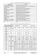
Note: Table 13-11 is based on internal angle compensation and not CT compensation. The table also
shows one set of input pairs (CT1 and CT2). All tests should be repeated with the other input pairs (CT1-
CT3, CT1-CT4, CT2-CT3, CT2-CT4, and CT3-CT4).
Phase Differential Restrained Minimum Pickup Trip
The test current will be a function of the internal angle and zero-sequence compensation and the tap
compensation. For the following test, you will apply a single-phase test current to one CT input circuit at a
time. It is only necessary to apply one phase per input to verify response and correctly entered settings.
For example, apply A phase for CT circuit 1 and 2 for Setting Group 0, B phase for CT circuit 1 and 2 for
Setting Group 1, etc., to verify all phases and all set points. Repeat tests for each of the CT input pairs.
Step 1:
Calculate test points for minimum-pickup test.
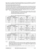
Calculate the test points using the compensation settings recorded in Step 1 and the
appropriate equations shown in Tables 13-12 through 13-14. Record the calculated
test point for each setting group before running the test.
Record the phases that will respond to the test.
Table 13-12. Differential Element Minpu Response to IA Test Current
CT Input Compensation
Element
Angle Comp
Ground Source
87A
87B
87C
Wye (None)
0 = No
Minpu* Tap
N/a
N/a
Wye (None)
1 = Yes
1.5* Minpu* Tap
3* Minpu* Tap
3* Minpu* Tap
DAB N/a
3* Minpu* Tap
N/a
3* Minpu* Tap
DAC N/a
3* Minpu* Tap
3* Minpu* Tap
N/a
Table 13-13. Differential Element Minpu Response to IB Test Current
CT Input Compensation
Element
Angle Comp
Ground Source
87A
87B
87C
Wye (None)
0 = No
N/a
Minpu* Tap
N/a
Wye (None)
1 = Yes
3* Minpu* Tap
1.5* Minpu* Tap
3* Minpu* Tap
DAB N/a
3* Minpu* Tap
3* Minpu* Tap
N/a
DAC N/a N/a
3* Minpu* Tap
3* Minpu* Tap
Table 13-14. Differential Element Minpu Response to IC Test Current
CT Input Compensation
Element
Angle Comp
Ground Source
87A
87B
87C
Wye (None)
0 = No
N/a
N/a
Minpu* Tap
Wye (None)
1 = Yes
3* Minpu* Tap
3* Minpu* Tap
1.5* Minpu* Tap
DAB N/a N/a
3* Minpu* Tap
3* Minpu* Tap
DAC N/a
3* Minpu* Tap
N/a
3* Minpu* Tap
Step 2: Test minimum pickup.
Slowly ramp up test current until the relay trips. Monitor an appropriate contact per the logic
settings and the trip LED. Record the value. Record if the proper phases targeted and if the
test was passed. The accuracy should be
4% or 0.75 milliamperes for 5-ampere units and
4% or 25 milliamperes for 1-ampere units.
Step 3: Repeat for each set of input pairs (CT1-CT3, CT1-CT4, CT2-CT3, CT2-CT4, and CT3-CT4).
Summary of Contents for BE1-CDS240
Page 2: ......
Page 8: ...vi BE1 CDS240 Introduction 9365200990 Rev F This page intentionally left blank ...
Page 38: ...1 28 BE1 CDS240 General Information 9365200990 Rev F This page intentionally left blank ...
Page 40: ...ii BE1 CDS240 Quick Start 9365200990 Rev F This page intentionally left blank ...
Page 152: ...ii BE1 CDS240 Metering 9365200990 Rev F This page intentionally left blank ...
Page 226: ...iv BE1 CDS240 Application 9365200990 Rev F This page intentionally left blank ...
Page 286: ...ii BE1 CDS240 Security 9365200990 Rev F This page intentionally left blank ...
Page 290: ...9 4 BE1 CDS240 Security 9365200990 Rev F This page intentionally left blank ...
Page 292: ...ii BE1 CDS240 Human Machine Interface 9365200990 Rev F This page intentionally left blank ...
Page 306: ...10 14 BE1 CDS240 Human Machine Interface 9365200990 Rev F This page intentionally left blank ...
Page 308: ...ii BE1 CDS240 ASCII Command Interface 9365200990 Rev F This page intentionally left blank ...
Page 342: ...11 34 BE1 CDS240 ASCII Command Interface 9365200990 Rev F This page intentionally left blank ...
Page 349: ...Figure 12 5 Horizontal Rack Mount Front View 9365200990 Rev F BE1 CDS240 Installation 12 5 ...
Page 361: ...Figure 12 17 Typical DC Connection Diagrams 9365200990 Rev F BE1 CDS240 Installation 12 17 ...
Page 372: ...12 28 BE1 CDS240 Installation 9365200990 Rev F This page intentionally left blank ...
Page 468: ...13 92 BE1 CDS240 Testing and Maintenance 9365200990 Rev F This page intentionally left blank ...
Page 512: ...14 42 BE1 CDS240 BESTCOMS Software 9365200990 Rev F This page intentionally left blank ...
Page 544: ...ii BE1 CDS240 Terminal Communication 9365200990 Rev F This page intentionally left blank ...
Page 550: ...ii BE1 CDS240 Settings Calculations 9365200990 Rev F This page intentionally left blank ...
Page 578: ...D 28 BE1 CDS240 Settings Calculations 9365200990 Rev F This page intentionally left blank ...
Page 579: ......

