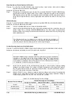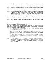
Phase Differential Restrained Slope Trip
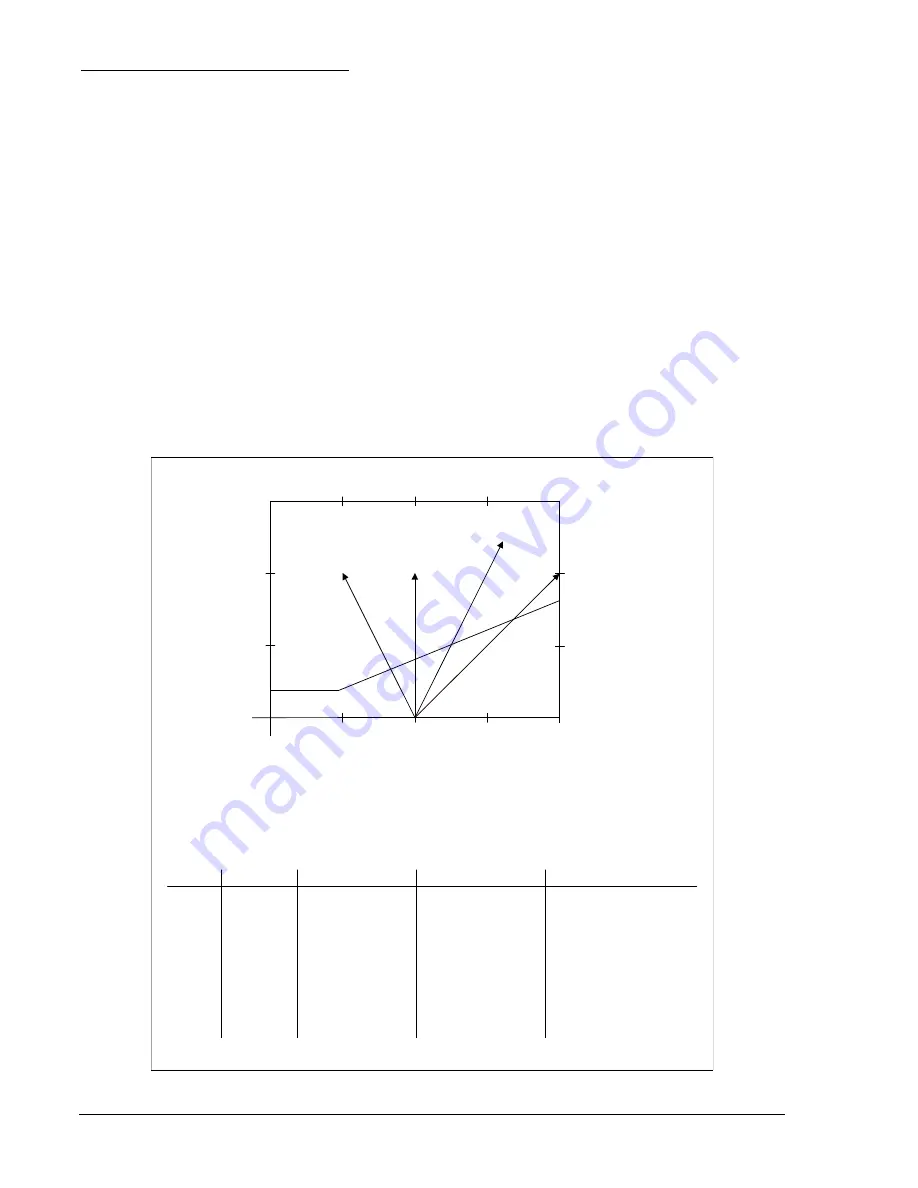
This test will verify the percentage restraint characteristic. Since each current input circuit and phase
protective element was verified in the preceding test, it is only necessary to test and verify the slope
characteristic on one phase element for each setting group. It is recommended, however, to check the
operation for each set of input pairs (CT1-CT2, CT1-CT3, CT1-CT4, CT2-CT3, CT2-CT4, and CT3-CT4).
The restrained slope test requires that you start from a balanced condition. To create the
Iop
(differential)
current, you will vary one test current upward or downward from this balanced condition. The test point at
which a trip should occur will depend upon whether you set the relay to operate on percent of maximum
restraint current or percent of average restraint current. It will also depend upon whether the
Iop
is to be
developed by increasing or decreasing one current source from balance. See Figure 13-3 for details.
Step 4:
Calculate the test starting point (balanced) for restrained slope test.
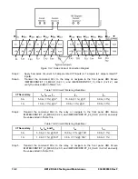
Step 4-1: Select and record the appropriate test connection from Table 13-15.
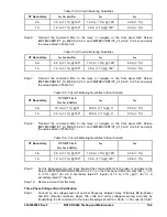
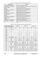
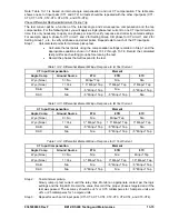
Step 4-2: Calculate the balanced starting test currents that are to be applied to each input circuit of the
relay. Use the appropriate equation from Table 13-11,
Test Current
, and record values before
starting the test. The equations provide a convenient starting balance point at two times tap.
Do this for each setting group.
Step 4-3: Check that the starting (balanced) test current at two times tap is not above the maximum
continuous current rating of the relay. If it is, adjust both starting test currents downward until
both are below this level. Use the same adjustment factor on both currents such that they
remain
balanced.
CDS Restraint Characteristic
MIN PU
slope
1
2
3
4
1
2
y
1MI
y
1AI
y
1MD
y
1AD
y
1MD
= I1 decreasing with maximum restraint
y
1MI
= I1 increasing with maximum restraint
y
1AD
= I1 decreasing with average restraint
y
1AI
= I1 increasing with average restraint
Condition
Restraint
Min PU?
Trip If Min PU
Trip If Slope
I1 = I2
Decrease I1
I1 = I2
Increase I1
I1 = I2
Decrease I1
I1 = I2
Increase I1
Maximum
Maximum
Average
I2<min pu/slope
I1 = I2/(1 - slope)
I2<min pu(1/slope + 1/2)
Average
I2<min pu(1/slope - 1/2)
I1 = I2*(1 - slope)
I2<min pu(1/slope - 1)
I1 = I2(1 - (2*slope/(2+slope)))
I1 = I2(1 + (2*slope/(2-slope)))
I1 = I2 - min pu
I1 = I2 + min pu
I1 = I2 + min pu
I1 = I2 - min pu
Ir
Iop
D2857-09.vsd
10-08-99
Iop = |I1 - I2|
Ir = max(|I1|,|I2|) for max restraint
Ir = (|I1|+|I2|)/2 for average restraint
Figure 13-3. Test Currents for Restrained Trip Test
13-16
90 Rev F
BE1-CDS240 Testing and Maintenance
93652009
Summary of Contents for BE1-CDS240
Page 2: ......
Page 8: ...vi BE1 CDS240 Introduction 9365200990 Rev F This page intentionally left blank ...
Page 38: ...1 28 BE1 CDS240 General Information 9365200990 Rev F This page intentionally left blank ...
Page 40: ...ii BE1 CDS240 Quick Start 9365200990 Rev F This page intentionally left blank ...
Page 152: ...ii BE1 CDS240 Metering 9365200990 Rev F This page intentionally left blank ...
Page 226: ...iv BE1 CDS240 Application 9365200990 Rev F This page intentionally left blank ...
Page 286: ...ii BE1 CDS240 Security 9365200990 Rev F This page intentionally left blank ...
Page 290: ...9 4 BE1 CDS240 Security 9365200990 Rev F This page intentionally left blank ...
Page 292: ...ii BE1 CDS240 Human Machine Interface 9365200990 Rev F This page intentionally left blank ...
Page 306: ...10 14 BE1 CDS240 Human Machine Interface 9365200990 Rev F This page intentionally left blank ...
Page 308: ...ii BE1 CDS240 ASCII Command Interface 9365200990 Rev F This page intentionally left blank ...
Page 342: ...11 34 BE1 CDS240 ASCII Command Interface 9365200990 Rev F This page intentionally left blank ...
Page 349: ...Figure 12 5 Horizontal Rack Mount Front View 9365200990 Rev F BE1 CDS240 Installation 12 5 ...
Page 361: ...Figure 12 17 Typical DC Connection Diagrams 9365200990 Rev F BE1 CDS240 Installation 12 17 ...
Page 372: ...12 28 BE1 CDS240 Installation 9365200990 Rev F This page intentionally left blank ...
Page 468: ...13 92 BE1 CDS240 Testing and Maintenance 9365200990 Rev F This page intentionally left blank ...
Page 512: ...14 42 BE1 CDS240 BESTCOMS Software 9365200990 Rev F This page intentionally left blank ...
Page 544: ...ii BE1 CDS240 Terminal Communication 9365200990 Rev F This page intentionally left blank ...
Page 550: ...ii BE1 CDS240 Settings Calculations 9365200990 Rev F This page intentionally left blank ...
Page 578: ...D 28 BE1 CDS240 Settings Calculations 9365200990 Rev F This page intentionally left blank ...
Page 579: ......

