

9365200990 Rev F
BE1-CDS240 Testing and Maintenance
13-69
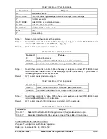
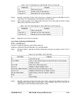
Command
Purpose
Y Confirm
overwrite.
SL-N=47
Sets 47 as custom logic name.
SL-27=0 Disables
27.
SL-59=0 Disables
59.
SL-47=1,0
Enables 47, disables blocking.
SP-60FL=ENA,PN
Removes 60FL block from 47 element.
SL-VO1=47T
Enables OUT1 to close for 47 trip.
SG-TRIG = 47T,47PU, 0
Enables 47 to log and trigger fault recording.
EXIT;Y
Exit and save settings.
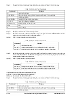
Step 2:
Using Table 13-71 as a guide, transmit the first row of setting commands to the relay.
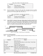
Table 13-71. 47 Pickup Settings
Pickup Settings
(Negative-Sequence Voltage)
Purpose
S0-47=24, 50ms
Sets 47 PU at 24 V, time delay at minimum
S0-47=30, 50ms
Sets 47 PU at 30 V, time delay at minimum
S0-47=36, 50ms
Sets 47 PU at 36 V, time delay at minimum
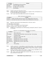
Step 3:
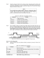
Prepare to monitor 47 function operation. Operation can be verified by monitoring OUT1.
Step 4:
Connect and apply a 50 Vac, single-phase voltage source to terminals B9 (A-phase) and B12
(Neutral). Refer to Figure 13-1 for terminal locations.
Step 5:
Negative-sequence voltage is 1/3 the phase voltage. Therefore, for a V2 setting of 24 volts,
the applied phase voltage will be 24 x 3 or 72 volts. Slowly increase the A-phase voltage until
OUT1 closes. Pickup should occur 2 percent or 1 volt of the pickup setting. Slowly
decrease the A-phase voltage until OUT1 opens. Dropout should occur between 97 and 98
percent of the actual pickup value. Verify the 47 target on the HMI.
Step 6:
Verify the pickup and dropout accuracy of the middle and upper 47 pickup settings.
Step 7:
(Optional.) Repeat Steps 2 through 6 for the B-phase and C-phase voltage inputs.
Step 8:
(Optional.) Repeat Steps 2 through 7 for Setting Groups 1, 2, and 3.
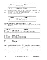
Negative-Sequence Voltage Timing Verification
Step 1:
Using Table 13-72 as a guide, transmit the first row of setting commands to the relay.
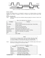
Table 13-72. 47 Pickup and Time Delay Settings
Pickup and Time Delay Settings
Purpose
S0-47=36,2S
Sets 47 PU at 36 V, 47 TD at 2 seconds
S0-47=,5S
Sets 47 TD at 5 seconds
S0-47=,10S
Sets 47 TD at 10 seconds
Step 2:
Prepare to monitor the 47 timings. Timing accuracy is verified by measuring the elapsed time
between a sensing voltage change and OUT1 closing.
Step 3:
Connect and apply a 100 Vac, single-phase voltage source to terminals B9 (A-phase) and B12
(Neutral). Refer to Figure 13-3 for terminal locations.
Step 4:
Step the A-phase voltage up to 115 volts. Measure the time delay and verify the accuracy of
the 47-time delay setting. Timing accuracy is +5 percent or +3 cycles of the time delay setting.
Step 5:
Repeat Step 4 for the middle and upper time delay settings of Table 13-72.
Summary of Contents for BE1-CDS240
Page 2: ......
Page 8: ...vi BE1 CDS240 Introduction 9365200990 Rev F This page intentionally left blank ...
Page 38: ...1 28 BE1 CDS240 General Information 9365200990 Rev F This page intentionally left blank ...
Page 40: ...ii BE1 CDS240 Quick Start 9365200990 Rev F This page intentionally left blank ...
Page 152: ...ii BE1 CDS240 Metering 9365200990 Rev F This page intentionally left blank ...
Page 226: ...iv BE1 CDS240 Application 9365200990 Rev F This page intentionally left blank ...
Page 286: ...ii BE1 CDS240 Security 9365200990 Rev F This page intentionally left blank ...
Page 290: ...9 4 BE1 CDS240 Security 9365200990 Rev F This page intentionally left blank ...
Page 292: ...ii BE1 CDS240 Human Machine Interface 9365200990 Rev F This page intentionally left blank ...
Page 306: ...10 14 BE1 CDS240 Human Machine Interface 9365200990 Rev F This page intentionally left blank ...
Page 308: ...ii BE1 CDS240 ASCII Command Interface 9365200990 Rev F This page intentionally left blank ...
Page 342: ...11 34 BE1 CDS240 ASCII Command Interface 9365200990 Rev F This page intentionally left blank ...
Page 349: ...Figure 12 5 Horizontal Rack Mount Front View 9365200990 Rev F BE1 CDS240 Installation 12 5 ...
Page 361: ...Figure 12 17 Typical DC Connection Diagrams 9365200990 Rev F BE1 CDS240 Installation 12 17 ...
Page 372: ...12 28 BE1 CDS240 Installation 9365200990 Rev F This page intentionally left blank ...
Page 468: ...13 92 BE1 CDS240 Testing and Maintenance 9365200990 Rev F This page intentionally left blank ...
Page 512: ...14 42 BE1 CDS240 BESTCOMS Software 9365200990 Rev F This page intentionally left blank ...
Page 544: ...ii BE1 CDS240 Terminal Communication 9365200990 Rev F This page intentionally left blank ...
Page 550: ...ii BE1 CDS240 Settings Calculations 9365200990 Rev F This page intentionally left blank ...
Page 578: ...D 28 BE1 CDS240 Settings Calculations 9365200990 Rev F This page intentionally left blank ...
Page 579: ......