


)
30
+
(
-
I
V
x
3
=
VARs
x
xy
3
sin
Equation 3-12
I
-
V
=
and
type
sensing
on
based
C
or
B
A,
=
y
and
x
where
x
xy
Measurement Functions Setup
Table 3-1 lists the measurement functions settings.
Table 3-1. Power System Measurement Function Settings
Setting Range
Increment
Unit of
Measure
Default
Nominal Frequency
50 or 60
1
Hertz
60
Phase Rotation
ABC, ACB
N/a
N/a
ABC
Nominal Voltage
50 - 250
1
Sec volts
69.3
Nominal Current
0.1 – 2 A for 1 A CT
0.5 – 10 A for 5 A CT
0.01 Sec
amps
1 A
5 A
VTP Setup, VT Ratio
1 - 10000
0.01
Turns ratio
1
VTP Setup, Connection
3W, 4W, AN, BN,
CN, AB, BC, CA
N/a N/a
4
W
VTP Setup, 27/59 Mode
PP, PN
N/a
N/a
PP
VTP Setup, 27R Mode
PP, PN
N/a
N/a
PP
VTP Setup, Winding
1 - 6
1
N/a
1
VTP Setup, Polarity
Normal or Reverse
N/a
N/a
Normal
CT Ratio, Inputs 1 - 4
1 - 50,000
1
Turns
1
CT Connection, Inputs 1 - 4
WYE, DAB, DAC,
GND
N/a N/a
Wye
CT Ratio, Independent Ground Input
1-50,000
1
Turns
1
Trans. Connection, Inputs 1 - 4
WYE, DAB, DAC,
ZAB, ZAC, NA, GND
N/a N/a
Wye
Ground Source, Inputs 1 - 4
0 = No, 1 = Yes
N/a
N/a
0
Trans. Rotation Comp, Inputs 1 - 4
A, B, C
N/a
N/a
A
Trans Differential Circuit, Inputs 1 - 4
P, S, N
N/a
N/a
P
Virtual Circuit Setup
0 - 13
1
N/a
0
GND is valid for CT 4 input only when configuring the BE1-CDS240 for a 2
nd
independent ground input.
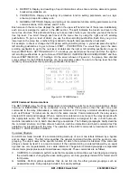
Power System / VT Setup
To enter Power System or VT settings, select
General Operation
from the
Screens
pull-down menu. Then
select the
Power System / VT Setup
tab. Refer to Figure 3-1.
3-4
BE1-CDS240 Input and Output Functions
9365200990 Rev F
Summary of Contents for BE1-CDS240
Page 2: ......
Page 8: ...vi BE1 CDS240 Introduction 9365200990 Rev F This page intentionally left blank ...
Page 38: ...1 28 BE1 CDS240 General Information 9365200990 Rev F This page intentionally left blank ...
Page 40: ...ii BE1 CDS240 Quick Start 9365200990 Rev F This page intentionally left blank ...
Page 152: ...ii BE1 CDS240 Metering 9365200990 Rev F This page intentionally left blank ...
Page 226: ...iv BE1 CDS240 Application 9365200990 Rev F This page intentionally left blank ...
Page 286: ...ii BE1 CDS240 Security 9365200990 Rev F This page intentionally left blank ...
Page 290: ...9 4 BE1 CDS240 Security 9365200990 Rev F This page intentionally left blank ...
Page 292: ...ii BE1 CDS240 Human Machine Interface 9365200990 Rev F This page intentionally left blank ...
Page 306: ...10 14 BE1 CDS240 Human Machine Interface 9365200990 Rev F This page intentionally left blank ...
Page 308: ...ii BE1 CDS240 ASCII Command Interface 9365200990 Rev F This page intentionally left blank ...
Page 342: ...11 34 BE1 CDS240 ASCII Command Interface 9365200990 Rev F This page intentionally left blank ...
Page 349: ...Figure 12 5 Horizontal Rack Mount Front View 9365200990 Rev F BE1 CDS240 Installation 12 5 ...
Page 361: ...Figure 12 17 Typical DC Connection Diagrams 9365200990 Rev F BE1 CDS240 Installation 12 17 ...
Page 372: ...12 28 BE1 CDS240 Installation 9365200990 Rev F This page intentionally left blank ...
Page 468: ...13 92 BE1 CDS240 Testing and Maintenance 9365200990 Rev F This page intentionally left blank ...
Page 512: ...14 42 BE1 CDS240 BESTCOMS Software 9365200990 Rev F This page intentionally left blank ...
Page 544: ...ii BE1 CDS240 Terminal Communication 9365200990 Rev F This page intentionally left blank ...
Page 550: ...ii BE1 CDS240 Settings Calculations 9365200990 Rev F This page intentionally left blank ...
Page 578: ...D 28 BE1 CDS240 Settings Calculations 9365200990 Rev F This page intentionally left blank ...
Page 579: ......


