C
B
A
D2837-15
12-22-98
ZONE OF
PROTECTION
POLARITY
INTO ZONE
WYE
DAB
DAC
I
B
I
A
N
I
C
I
A
-I
B
I
B
-I
C
I
C
-I
A
I
A
-I
C
I
B
-I
A
I
C
-I
B
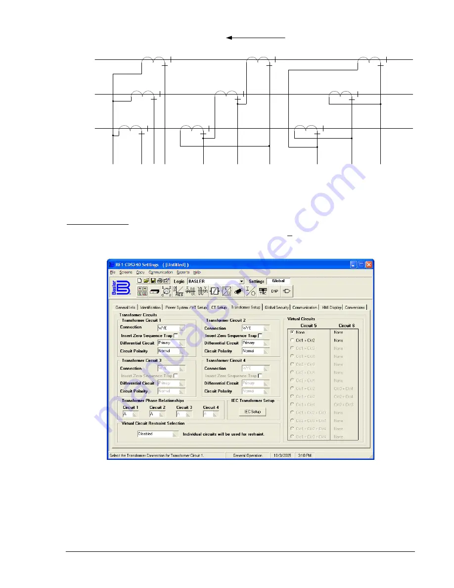
Figure 3-3. CT Connections
Transformer Setup
To enter Transformer settings, select
General Operation
from the
Screens
pull-down menu. Then select
the
Transformer Setup
tab. Refer to Figure 3-4.
Figure 3-4. General Operation Screen, Transformer Setup Tab
Use the pull down menus and check boxes to setup transformer circuits. Settings can also be made using
the HMI Screen 6.3.1.3, \SETUP\PWR_S\CONN\TXC, or from the ASCII command interface using the
SG-CKT command. For each circuit, you can set
Connection, Insert Zero Sequence Trap, Differential
Circuit,
and
Circuit Polarity.
You can also set
Transformer Phase Relationships, Individual circuits to be
used for restraint,
and
Virtual Circuits.
9365200990 Rev F
BE1-CDS240 Input and Output Functions
3-7
Summary of Contents for BE1-CDS240
Page 2: ......
Page 8: ...vi BE1 CDS240 Introduction 9365200990 Rev F This page intentionally left blank ...
Page 38: ...1 28 BE1 CDS240 General Information 9365200990 Rev F This page intentionally left blank ...
Page 40: ...ii BE1 CDS240 Quick Start 9365200990 Rev F This page intentionally left blank ...
Page 152: ...ii BE1 CDS240 Metering 9365200990 Rev F This page intentionally left blank ...
Page 226: ...iv BE1 CDS240 Application 9365200990 Rev F This page intentionally left blank ...
Page 286: ...ii BE1 CDS240 Security 9365200990 Rev F This page intentionally left blank ...
Page 290: ...9 4 BE1 CDS240 Security 9365200990 Rev F This page intentionally left blank ...
Page 292: ...ii BE1 CDS240 Human Machine Interface 9365200990 Rev F This page intentionally left blank ...
Page 306: ...10 14 BE1 CDS240 Human Machine Interface 9365200990 Rev F This page intentionally left blank ...
Page 308: ...ii BE1 CDS240 ASCII Command Interface 9365200990 Rev F This page intentionally left blank ...
Page 342: ...11 34 BE1 CDS240 ASCII Command Interface 9365200990 Rev F This page intentionally left blank ...
Page 349: ...Figure 12 5 Horizontal Rack Mount Front View 9365200990 Rev F BE1 CDS240 Installation 12 5 ...
Page 361: ...Figure 12 17 Typical DC Connection Diagrams 9365200990 Rev F BE1 CDS240 Installation 12 17 ...
Page 372: ...12 28 BE1 CDS240 Installation 9365200990 Rev F This page intentionally left blank ...
Page 468: ...13 92 BE1 CDS240 Testing and Maintenance 9365200990 Rev F This page intentionally left blank ...
Page 512: ...14 42 BE1 CDS240 BESTCOMS Software 9365200990 Rev F This page intentionally left blank ...
Page 544: ...ii BE1 CDS240 Terminal Communication 9365200990 Rev F This page intentionally left blank ...
Page 550: ...ii BE1 CDS240 Settings Calculations 9365200990 Rev F This page intentionally left blank ...
Page 578: ...D 28 BE1 CDS240 Settings Calculations 9365200990 Rev F This page intentionally left blank ...
Page 579: ......

