Retrieving Instantaneous Overcurrent Status from the Relay
The status of each logic variable can be determined from the ASCII command interface using the RG-
STAT command or using BESTCOMS
Metering
screen. See Section 6,
Reporting and Alarm Functions,
General Status Reporting,
for more information.
NOTE
When changing settings with the relay in service, an error message (PU TOO
LOW) will be generated if the new setting is within approximately 90% of the
metered current level. This is intended to prevent the user from inadvertently
causing a trip when changing a setting.
51 - Time Overcurrent Protection
There are four independent functions for phase (51P, 151P, 251P, 351P), five for neutral (51N, 151N,
251N, 351N, 451N), and four for negative-sequence (51Q, 151Q, 251Q, 351Q) inverse time overcurrent
protection. Each function can be attached to any of the four hardware CT input circuits or the two virtual
current circuits by the BESTlogic mode
setting. See Section 3,
Inputs and Outputs
, for
details on the virtual current circuits.
D2843-41
08-18-03
BLK
51PT
SL-51P
LOGIC
51PPU
Mode =
0-disable
1-ct ckt 1
2-ct ckt 2
3-ct ckt 3
4-ct ckt 4
5-ct ckt 5
6-ct ckt 6
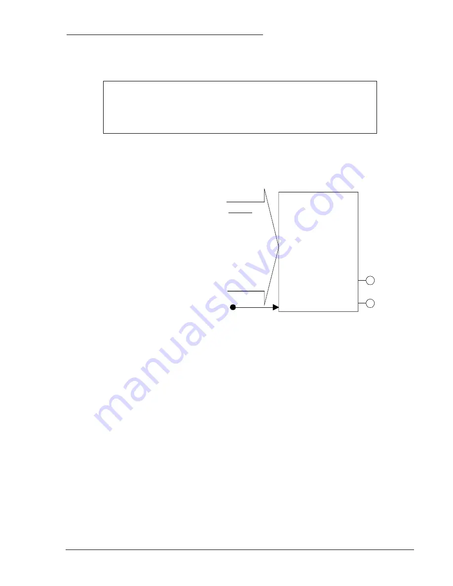
Figure 4-23 shows the 51P (phase time
overcurrent) as a typical 51 function. Each of
the nine independent functions has two logic
outputs #51nPU (picked up) and #51nT (trip)
where n indicates whether it is a P (phase), N
(neutral), or Q (negative-sequence). The #
differentiates between the protective functions
(51, 151, etc).
Figure 4-23. Time Overcurrent Logic Block
A
BLK
(Block) logic input is provided to each function that can be used to disable the function. When this
expression is TRUE, the function is disabled by forcing the outputs to logic zero and resetting the timers
to zero. For example, this could be used similar to a torque control contact on an electromechanical relay.
Each inverse time overcurrent function has a pickup, a time dial, and a curve setting. See Appendix A,
Time Overcurrent Characteristic Curves,
for details on each of the curves available. To make the
protective element use integrated reset and emulate an electromechanical induction disk reset
characteristic, the user can append an R to the selected time current characteristic curve. A
programmable curve is available that can be used to create a custom curve by selecting coefficients in
the inverse time characteristic equation.
When the measured current is above the pickup threshold, the pickup logic output, 51PPU (for example)
= TRUE and inverse timing is started per the selected characteristic. If the current stays above pickup
until the function times out, the trip logic output, 51PT (for example) = TRUE. If the current falls below the
dropout ratio, which is 95%, the function will either reset instantaneously or begin timing to reset
depending on the user’s setting.
The phase overcurrent protective functions use the highest of the three measured phase currents. If the
current is above the pickup setting for any one phase, the pickup logic output is asserted. If the trip
condition is TRUE, the trip logic output is asserted.
If the target is enabled for the function block, the target reporting function will record a target for all
phases that are above pickup when the protective function trip output is TRUE and the fault recording
function trip logic expression is TRUE. See Section 6,
Reporting and Alarm Functions, Fault Reporting,
for more details on the target reporting function.
9365200990 Rev F
BE1-CDS240 Protection and Control
4-27
Summary of Contents for BE1-CDS240
Page 2: ......
Page 8: ...vi BE1 CDS240 Introduction 9365200990 Rev F This page intentionally left blank ...
Page 38: ...1 28 BE1 CDS240 General Information 9365200990 Rev F This page intentionally left blank ...
Page 40: ...ii BE1 CDS240 Quick Start 9365200990 Rev F This page intentionally left blank ...
Page 152: ...ii BE1 CDS240 Metering 9365200990 Rev F This page intentionally left blank ...
Page 226: ...iv BE1 CDS240 Application 9365200990 Rev F This page intentionally left blank ...
Page 286: ...ii BE1 CDS240 Security 9365200990 Rev F This page intentionally left blank ...
Page 290: ...9 4 BE1 CDS240 Security 9365200990 Rev F This page intentionally left blank ...
Page 292: ...ii BE1 CDS240 Human Machine Interface 9365200990 Rev F This page intentionally left blank ...
Page 306: ...10 14 BE1 CDS240 Human Machine Interface 9365200990 Rev F This page intentionally left blank ...
Page 308: ...ii BE1 CDS240 ASCII Command Interface 9365200990 Rev F This page intentionally left blank ...
Page 342: ...11 34 BE1 CDS240 ASCII Command Interface 9365200990 Rev F This page intentionally left blank ...
Page 349: ...Figure 12 5 Horizontal Rack Mount Front View 9365200990 Rev F BE1 CDS240 Installation 12 5 ...
Page 361: ...Figure 12 17 Typical DC Connection Diagrams 9365200990 Rev F BE1 CDS240 Installation 12 17 ...
Page 372: ...12 28 BE1 CDS240 Installation 9365200990 Rev F This page intentionally left blank ...
Page 468: ...13 92 BE1 CDS240 Testing and Maintenance 9365200990 Rev F This page intentionally left blank ...
Page 512: ...14 42 BE1 CDS240 BESTCOMS Software 9365200990 Rev F This page intentionally left blank ...
Page 544: ...ii BE1 CDS240 Terminal Communication 9365200990 Rev F This page intentionally left blank ...
Page 550: ...ii BE1 CDS240 Settings Calculations 9365200990 Rev F This page intentionally left blank ...
Page 578: ...D 28 BE1 CDS240 Settings Calculations 9365200990 Rev F This page intentionally left blank ...
Page 579: ......


