


1-6
BE1-CDS240 General Information
9365200990 Rev F
Version Report
The version of the embedded software (firmware) is available from the front panel interface HMI
or the communications ports.
The unit serial number and style number is also available from the communications ports.
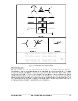
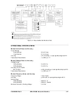
BESTlogic Programmable Logic
Each of the protection and control functions in the BE1-CDS240 is implemented in an
independent function that is equivalent to its single function, discrete device counterpart so that it
is immediately familiar to the protection engineer. Each independent function block has all of the
inputs and outputs that the discrete component counterpart might have.
Programming BESTlogic is equivalent to choosing the devices required by your protection and
control scheme and drawing schematic diagrams to connect the inputs and outputs to obtain the
desired operational logic.
One preprogrammed embedded logic scheme (in the relay firmware) and a library of
preprogrammed logic schemes in BESTCOMS are provided and thoroughly documented in
Section 8,
Applications
. To set the relay to one of the BESTCOMS library applications, simply
select the logic scheme and upload it to the relay.
A set of custom logic settings is also available for you to optimize the functionality to the specific
needs of your operation's practices and power system requirements.
Security
Security can be defined for three distinct functional access areas: Settings, Reports, and Control.
Each functional access area can be assigned a password. A global password provides access to
all three functional areas. Each of these four passwords can be unique or multiple functional
access areas can have the same password.
Allowing the user to restrict access to any of the three functional access areas from only specific
communication ports provides a second dimension of security. For example, you could set
security to deny access to control commands from the rear RS-232 port that is connected through
a modem to a telephone line.
Security settings only affect write access. You have read access from any port to any area.
Human-Machine Interface
Each BE1-CDS240 comes with a front panel display with LED (light emitting diode) indicators for
power, relay trouble alarm, minor alarm, major alarm, and trip. Each BE1-CDS240 also comes
with the software application program BESTCOMS for the CDS240. This program is a user
friendly, Windows
based program that makes relay setup and support very easy.
The programmable graphical LCD (liquid crystal display) allows the relay to replace local
indication and control functions such as panel metering, alarm annunciation, and control
switches.
The human-machine interface (HMI) is set up in a menu tree with four scrolling buttons for
navigation.
Edit
and
Reset
pushbuttons provide access to change parameters and reset targets,
alarms and other registers. Scrolling buttons are used for data entry when in edit mode. Edit
mode is indicated by an LED on the
Edit
button.
The LCD has automatic priority logic to govern what is being displayed on the screen so that
when an operator approaches, the information of most interest is automatically displayed without
having to navigate the menu structure. The priorities are targets, then alarms and then the
programmable automatic scrolling list.
Up to 16 screens can be defined in the programmable, automatic scroll list.
ASCII Command Interface
Three (3) independent, isolated communications ports provide access to all functions in the relay.
Com 0 is a 9-pin RS-232 port located on the front of the case. Com 1 is a 9-pin RS-232 port
located on the back of the case. Com 2 is a three-terminal, RS-485 port located on the back of
the case.
Standard communications is an ASCII command interface to allow easy interaction with the relay
using standard, off the shelf, communications software.
Summary of Contents for BE1-CDS240
Page 2: ......
Page 8: ...vi BE1 CDS240 Introduction 9365200990 Rev F This page intentionally left blank ...
Page 38: ...1 28 BE1 CDS240 General Information 9365200990 Rev F This page intentionally left blank ...
Page 40: ...ii BE1 CDS240 Quick Start 9365200990 Rev F This page intentionally left blank ...
Page 152: ...ii BE1 CDS240 Metering 9365200990 Rev F This page intentionally left blank ...
Page 226: ...iv BE1 CDS240 Application 9365200990 Rev F This page intentionally left blank ...
Page 286: ...ii BE1 CDS240 Security 9365200990 Rev F This page intentionally left blank ...
Page 290: ...9 4 BE1 CDS240 Security 9365200990 Rev F This page intentionally left blank ...
Page 292: ...ii BE1 CDS240 Human Machine Interface 9365200990 Rev F This page intentionally left blank ...
Page 306: ...10 14 BE1 CDS240 Human Machine Interface 9365200990 Rev F This page intentionally left blank ...
Page 308: ...ii BE1 CDS240 ASCII Command Interface 9365200990 Rev F This page intentionally left blank ...
Page 342: ...11 34 BE1 CDS240 ASCII Command Interface 9365200990 Rev F This page intentionally left blank ...
Page 349: ...Figure 12 5 Horizontal Rack Mount Front View 9365200990 Rev F BE1 CDS240 Installation 12 5 ...
Page 361: ...Figure 12 17 Typical DC Connection Diagrams 9365200990 Rev F BE1 CDS240 Installation 12 17 ...
Page 372: ...12 28 BE1 CDS240 Installation 9365200990 Rev F This page intentionally left blank ...
Page 468: ...13 92 BE1 CDS240 Testing and Maintenance 9365200990 Rev F This page intentionally left blank ...
Page 512: ...14 42 BE1 CDS240 BESTCOMS Software 9365200990 Rev F This page intentionally left blank ...
Page 544: ...ii BE1 CDS240 Terminal Communication 9365200990 Rev F This page intentionally left blank ...
Page 550: ...ii BE1 CDS240 Settings Calculations 9365200990 Rev F This page intentionally left blank ...
Page 578: ...D 28 BE1 CDS240 Settings Calculations 9365200990 Rev F This page intentionally left blank ...
Page 579: ......