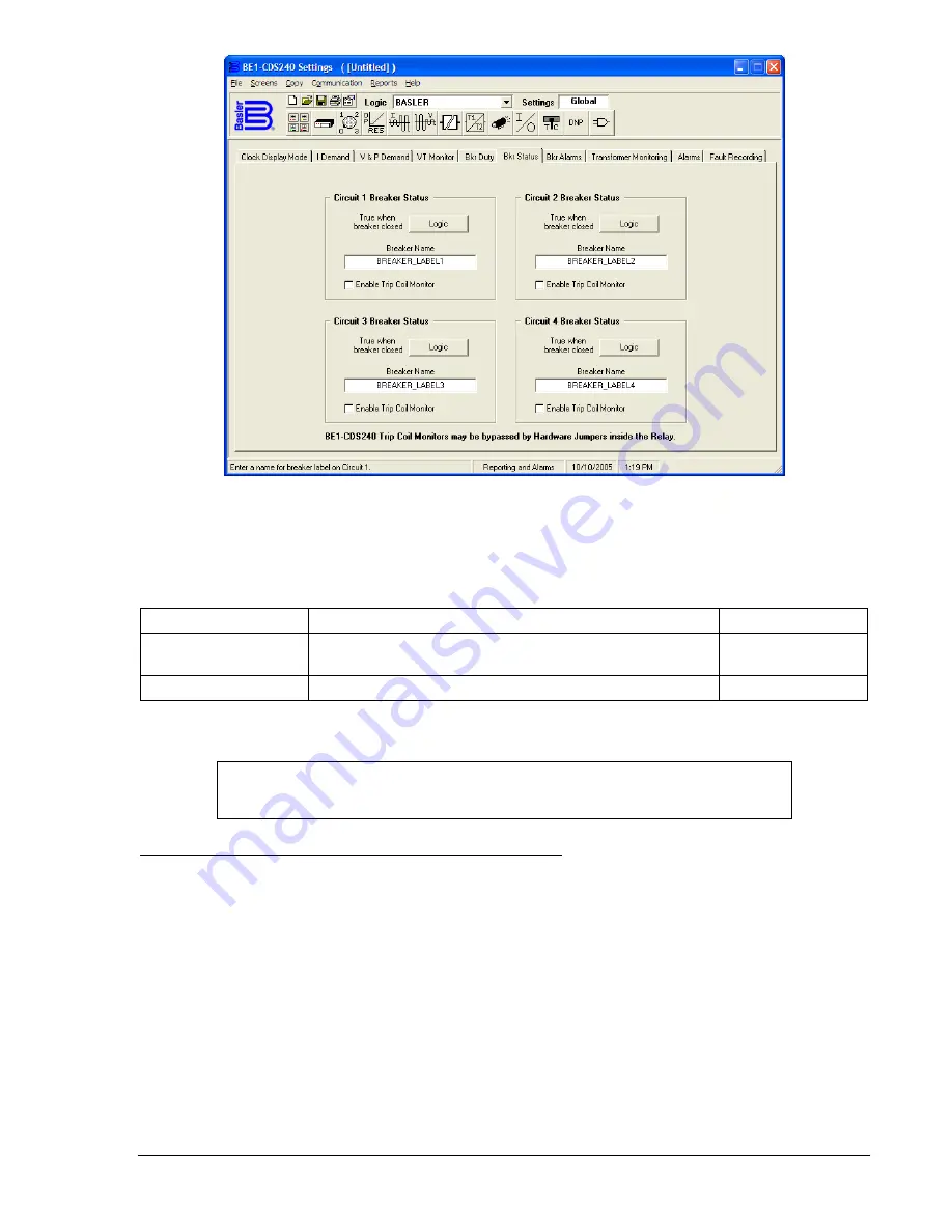
Figure 6-9. Reporting and Alarms Screen, Bkr Status Tab
Table 6-10 lists the settings for the breaker status reporting function.
Table 6-10. Breaker Status Reporting Settings
Setting Range/Purpose
Default
Breaker Closed Logic
Logic expression that is TRUE when the breaker is
closed (e.g., 52a logic)
0
Breaker Label
16 character alpha/numerical label (name)
BREAKER_LABEL
NOTE
The NOT symbol (/) is applied to the variable immediately following the symbol.
Retrieving Breaker Status and Operation Counter Information
The current breaker status can be read from HMI Screen 1.4.5, \STAT\OPER\BKR and from the ASCII
command interface using the RG-STAT or RG-BREAKER command. The paragraphs on
General Status
Reporting
in this section provide more information on this command.
The current value of the breaker operations counter register can be read from HMI Screen 4.3.1,
\REPRT\BRPTS\STATUS. Pressing the
Edit
key allows the user to enter a number into the register to
preset it to a value to match an existing mechanical cyclometer on the breaker mechanism. Write access
to the reports functional area must be gained to edit this value at the HMI. The current value of the
breaker operations counter can also be read or preset from the ASCII command interface using the RB-
OPCNTR (report breaker, operations counter) command.
The breaker operations counter can be monitored to give an alarm when the value exceeds a threshold.
See
Breaker Alarms
in this section for more information on this feature.
Breaker Duty Monitoring
When the breaker opens, the N
th
power of the current interrupted in each pole of the circuit breaker is
accumulated by the breaker duty monitor. Breaker opening is defined by the breaker status monitoring
9365200990 Rev F
BE1-CDS240 Reporting and Alarm Functions
6-19
Summary of Contents for BE1-CDS240
Page 2: ......
Page 8: ...vi BE1 CDS240 Introduction 9365200990 Rev F This page intentionally left blank ...
Page 38: ...1 28 BE1 CDS240 General Information 9365200990 Rev F This page intentionally left blank ...
Page 40: ...ii BE1 CDS240 Quick Start 9365200990 Rev F This page intentionally left blank ...
Page 152: ...ii BE1 CDS240 Metering 9365200990 Rev F This page intentionally left blank ...
Page 226: ...iv BE1 CDS240 Application 9365200990 Rev F This page intentionally left blank ...
Page 286: ...ii BE1 CDS240 Security 9365200990 Rev F This page intentionally left blank ...
Page 290: ...9 4 BE1 CDS240 Security 9365200990 Rev F This page intentionally left blank ...
Page 292: ...ii BE1 CDS240 Human Machine Interface 9365200990 Rev F This page intentionally left blank ...
Page 306: ...10 14 BE1 CDS240 Human Machine Interface 9365200990 Rev F This page intentionally left blank ...
Page 308: ...ii BE1 CDS240 ASCII Command Interface 9365200990 Rev F This page intentionally left blank ...
Page 342: ...11 34 BE1 CDS240 ASCII Command Interface 9365200990 Rev F This page intentionally left blank ...
Page 349: ...Figure 12 5 Horizontal Rack Mount Front View 9365200990 Rev F BE1 CDS240 Installation 12 5 ...
Page 361: ...Figure 12 17 Typical DC Connection Diagrams 9365200990 Rev F BE1 CDS240 Installation 12 17 ...
Page 372: ...12 28 BE1 CDS240 Installation 9365200990 Rev F This page intentionally left blank ...
Page 468: ...13 92 BE1 CDS240 Testing and Maintenance 9365200990 Rev F This page intentionally left blank ...
Page 512: ...14 42 BE1 CDS240 BESTCOMS Software 9365200990 Rev F This page intentionally left blank ...
Page 544: ...ii BE1 CDS240 Terminal Communication 9365200990 Rev F This page intentionally left blank ...
Page 550: ...ii BE1 CDS240 Settings Calculations 9365200990 Rev F This page intentionally left blank ...
Page 578: ...D 28 BE1 CDS240 Settings Calculations 9365200990 Rev F This page intentionally left blank ...
Page 579: ......


