


DIFFERENTIAL PROTECTION APPLICATION CONSIDERATIONS
The principle of current differential relaying is simple in concept. Measure the current flowing into the
protected zone and the current flowing out of the protected zone. These should match exactly (sum to
zero). If they do not, there is a fault within the protected zone. The mismatch in current that results from
the instantaneous summation of the currents into and out of the zone of protection is called the differential
current or the operate current. While the concept is simple, several difficulties present challenges to the
application of this type of protection. The BE1-CDS240 Current Differential System provides several
features that allow it to easily address these complications and enable it to be used in all differential
applications including transformer protection.
Problem 1: False Differential Current Due to Poor CT Performance
General
The principle of current differential relaying requires accurate measurement of the currents entering and
exiting the zone of protection. During fault conditions where high current is flowing through the zone of
protection, a CT may saturate and not faithfully reproduce the current flowing in the primary system. This
will cause a false differential current to be seen by the differential relay.
BE1-CDS240 Solution
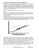
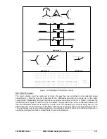
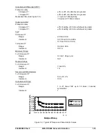
The percentage restrained differential characteristic, shown in Figure 1-1, is applied in this application.
The differential current required to cause a trip is a percentage of the restraint current. The restraint
current is a measure of the current flowing into or through the zone of protection. Thus for higher levels of
restraint current, where the CTs may be subject to saturation, higher levels of differential current must be
seen to cause a trip. The percentage restraint is often called the slope characteristic.
Figure 1-1. Restrained Differential Characteristic
The BE1-CDS240 relay has two settable restraint current calculation methods: average and maximum.
Average restraint emulates the operating characteristics of common electromechanical relays. Maximum
restraint is recommended because it uses the current from the best performing CT to determine the
restraint to use during a fault condition. In addition, digital technology provides a transient monitor
function that enables the BE1-CDS240 relay to detect the onset of CT saturation to ride through the
condition to further enhance security from misoperation caused by poorly performing CTs.
Finally, Basler Electric addresses the source of false differential current at its roots. Active CT technology
used on the current inputs provides low burden to extend the linear range of power system CTs and wide
dynamic range to reduce measurement errors at high current levels. Sixteen bit ADC performance and
digital anti-aliasing filters also contribute to minimizing magnitude and angle measurement errors.
1-8
BE1-CDS240 General Information
9365200990 Rev F
Summary of Contents for BE1-CDS240
Page 2: ......
Page 8: ...vi BE1 CDS240 Introduction 9365200990 Rev F This page intentionally left blank ...
Page 38: ...1 28 BE1 CDS240 General Information 9365200990 Rev F This page intentionally left blank ...
Page 40: ...ii BE1 CDS240 Quick Start 9365200990 Rev F This page intentionally left blank ...
Page 152: ...ii BE1 CDS240 Metering 9365200990 Rev F This page intentionally left blank ...
Page 226: ...iv BE1 CDS240 Application 9365200990 Rev F This page intentionally left blank ...
Page 286: ...ii BE1 CDS240 Security 9365200990 Rev F This page intentionally left blank ...
Page 290: ...9 4 BE1 CDS240 Security 9365200990 Rev F This page intentionally left blank ...
Page 292: ...ii BE1 CDS240 Human Machine Interface 9365200990 Rev F This page intentionally left blank ...
Page 306: ...10 14 BE1 CDS240 Human Machine Interface 9365200990 Rev F This page intentionally left blank ...
Page 308: ...ii BE1 CDS240 ASCII Command Interface 9365200990 Rev F This page intentionally left blank ...
Page 342: ...11 34 BE1 CDS240 ASCII Command Interface 9365200990 Rev F This page intentionally left blank ...
Page 349: ...Figure 12 5 Horizontal Rack Mount Front View 9365200990 Rev F BE1 CDS240 Installation 12 5 ...
Page 361: ...Figure 12 17 Typical DC Connection Diagrams 9365200990 Rev F BE1 CDS240 Installation 12 17 ...
Page 372: ...12 28 BE1 CDS240 Installation 9365200990 Rev F This page intentionally left blank ...
Page 468: ...13 92 BE1 CDS240 Testing and Maintenance 9365200990 Rev F This page intentionally left blank ...
Page 512: ...14 42 BE1 CDS240 BESTCOMS Software 9365200990 Rev F This page intentionally left blank ...
Page 544: ...ii BE1 CDS240 Terminal Communication 9365200990 Rev F This page intentionally left blank ...
Page 550: ...ii BE1 CDS240 Settings Calculations 9365200990 Rev F This page intentionally left blank ...
Page 578: ...D 28 BE1 CDS240 Settings Calculations 9365200990 Rev F This page intentionally left blank ...
Page 579: ......


