


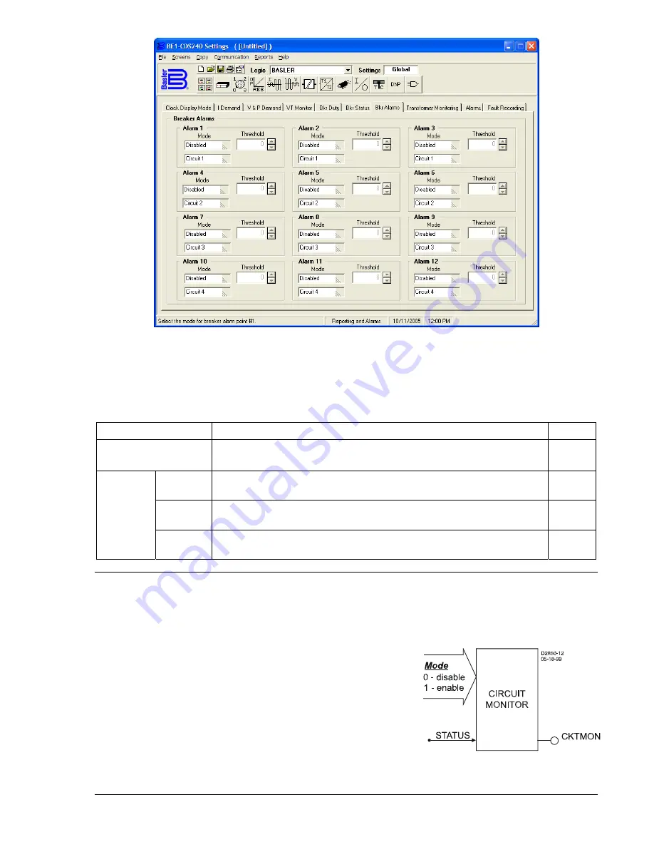
Figure 6-13. Reporting and Alarms Screen, Bkr Alarms Tab
Table 6-13 summarizes the Breaker Alarms settings.
Table 6-13. Breaker Alarms Settings
Setting Range/Purpose
Default
Mode
0 = Disabled
1 = Percent Duty
2 = Number of Operations
3 = Breaker Clearing Time
0
Point 1
Mode
0 to 100 in percent, increment = 0.01
0
Point 2
Mode
9365200990 Rev F
BE1-CDS240 Reporting and Alarm Functions
6-25
0 to 99,999 in operations, increment = 1
0
Threshold
Point 3
Mode
0, 20 to 1,000 in milliseconds (m), seconds (s), or cycles (c). Setting
is reported in milliseconds if less than 1 seconds.
0
TRIP CIRCUIT MONITOR
The trip circuit voltage and continuity monitoring function monitors the trip circuit for voltage and
continuity. If a breaker is closed or the 86 Lockout relay is reset and no voltage is detected across the trip
contacts, then either the fuse supplying the circuit is blown or there is a loss of continuity in the trip coil
circuit.
The trip circuit monitor function obtains the breaker status from a
programmable setting, which is set using the <Trip Coil Enable>
parameter in the SB-LOGIC command. The detector circuit used
by the trip circuit monitoring function is internally connected in
parallel with Contact Outputs 7-10. The monitor circuits draw less
than two milliamperes of current through the trip coil when the
breaker is closed. If this current flow presents a problem for the
application, the monitor circuits can be physically disconnected by
Connectors P5, P6, P7, and P8. Figure 6-14 shows the trip
circuit monitor logic.
Figure 6-14. Trip Circuit Monitor Logic
Summary of Contents for BE1-CDS240
Page 2: ......
Page 8: ...vi BE1 CDS240 Introduction 9365200990 Rev F This page intentionally left blank ...
Page 38: ...1 28 BE1 CDS240 General Information 9365200990 Rev F This page intentionally left blank ...
Page 40: ...ii BE1 CDS240 Quick Start 9365200990 Rev F This page intentionally left blank ...
Page 152: ...ii BE1 CDS240 Metering 9365200990 Rev F This page intentionally left blank ...
Page 226: ...iv BE1 CDS240 Application 9365200990 Rev F This page intentionally left blank ...
Page 286: ...ii BE1 CDS240 Security 9365200990 Rev F This page intentionally left blank ...
Page 290: ...9 4 BE1 CDS240 Security 9365200990 Rev F This page intentionally left blank ...
Page 292: ...ii BE1 CDS240 Human Machine Interface 9365200990 Rev F This page intentionally left blank ...
Page 306: ...10 14 BE1 CDS240 Human Machine Interface 9365200990 Rev F This page intentionally left blank ...
Page 308: ...ii BE1 CDS240 ASCII Command Interface 9365200990 Rev F This page intentionally left blank ...
Page 342: ...11 34 BE1 CDS240 ASCII Command Interface 9365200990 Rev F This page intentionally left blank ...
Page 349: ...Figure 12 5 Horizontal Rack Mount Front View 9365200990 Rev F BE1 CDS240 Installation 12 5 ...
Page 361: ...Figure 12 17 Typical DC Connection Diagrams 9365200990 Rev F BE1 CDS240 Installation 12 17 ...
Page 372: ...12 28 BE1 CDS240 Installation 9365200990 Rev F This page intentionally left blank ...
Page 468: ...13 92 BE1 CDS240 Testing and Maintenance 9365200990 Rev F This page intentionally left blank ...
Page 512: ...14 42 BE1 CDS240 BESTCOMS Software 9365200990 Rev F This page intentionally left blank ...
Page 544: ...ii BE1 CDS240 Terminal Communication 9365200990 Rev F This page intentionally left blank ...
Page 550: ...ii BE1 CDS240 Settings Calculations 9365200990 Rev F This page intentionally left blank ...
Page 578: ...D 28 BE1 CDS240 Settings Calculations 9365200990 Rev F This page intentionally left blank ...
Page 579: ......


