


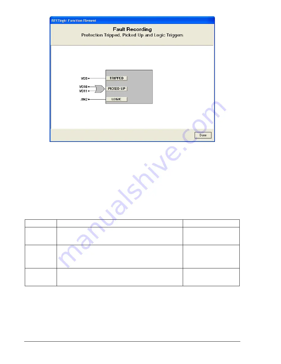
Figure 6-17. BESTlogic Function Element Screen, Fault Recording
To connect the function's inputs, select the button for the corresponding input in the
BESTlogic Function
Element
screen. The
BESTlogic Expression Builder
screen will open. Select the expression type to be
used. Then, select the BESTlogic variable, or series of variables to be connected to the input. Select
Save
when finished to return to the
BESTlogic Function Element
screen. For more details on the
BESTlogic Expression Builder
, see Section 7,
BESTlogic Programmable Logic
. Select
Done
when the
settings have been completely edited. Trigger settings for fault reports are made using the SG-TRIGGER
(settings-general, trigger) command.
Table 6-14 lists the function's trigger settings.
Table 6-14. Fault Reporting Trigger Settings
Function Purpose
Default
Logic expression used to define Trip fault reporting
condition. When this expression becomes TRUE (1), it
triggers data recording and illuminates the Trip LED.
BFT1+BFT2+BFT3+
BFT4+VO11
TRIPPED
Logic expression used to define Pickup fault reporting
condition. When this expression becomes TRUE (1), it
initiates the pickup timing sequence and the Trip LED will
flash on and off.
BFRT1+BFRT2+BFRT3+
BFRT4+VO12
PICKED UP
Logic expression used to define the trigger for fault
reporting when relay is not picked up. When this expression
is TRUE (1), fault reporting is triggered.
0
LOGIC
Targets
Each protective function (see Table 6-15) logs target information to the fault reporting function when a trip
condition occurs and the trip output of the function block becomes TRUE (refer to Figure 6-11 and Table
6-10, call-out B). Target information can be viewed and reset at the HMI and through the communication
ports.
6-28
BE1-CDS240 Reporting and Alarm Functions
9365200990 Rev F
Summary of Contents for BE1-CDS240
Page 2: ......
Page 8: ...vi BE1 CDS240 Introduction 9365200990 Rev F This page intentionally left blank ...
Page 38: ...1 28 BE1 CDS240 General Information 9365200990 Rev F This page intentionally left blank ...
Page 40: ...ii BE1 CDS240 Quick Start 9365200990 Rev F This page intentionally left blank ...
Page 152: ...ii BE1 CDS240 Metering 9365200990 Rev F This page intentionally left blank ...
Page 226: ...iv BE1 CDS240 Application 9365200990 Rev F This page intentionally left blank ...
Page 286: ...ii BE1 CDS240 Security 9365200990 Rev F This page intentionally left blank ...
Page 290: ...9 4 BE1 CDS240 Security 9365200990 Rev F This page intentionally left blank ...
Page 292: ...ii BE1 CDS240 Human Machine Interface 9365200990 Rev F This page intentionally left blank ...
Page 306: ...10 14 BE1 CDS240 Human Machine Interface 9365200990 Rev F This page intentionally left blank ...
Page 308: ...ii BE1 CDS240 ASCII Command Interface 9365200990 Rev F This page intentionally left blank ...
Page 342: ...11 34 BE1 CDS240 ASCII Command Interface 9365200990 Rev F This page intentionally left blank ...
Page 349: ...Figure 12 5 Horizontal Rack Mount Front View 9365200990 Rev F BE1 CDS240 Installation 12 5 ...
Page 361: ...Figure 12 17 Typical DC Connection Diagrams 9365200990 Rev F BE1 CDS240 Installation 12 17 ...
Page 372: ...12 28 BE1 CDS240 Installation 9365200990 Rev F This page intentionally left blank ...
Page 468: ...13 92 BE1 CDS240 Testing and Maintenance 9365200990 Rev F This page intentionally left blank ...
Page 512: ...14 42 BE1 CDS240 BESTCOMS Software 9365200990 Rev F This page intentionally left blank ...
Page 544: ...ii BE1 CDS240 Terminal Communication 9365200990 Rev F This page intentionally left blank ...
Page 550: ...ii BE1 CDS240 Settings Calculations 9365200990 Rev F This page intentionally left blank ...
Page 578: ...D 28 BE1 CDS240 Settings Calculations 9365200990 Rev F This page intentionally left blank ...
Page 579: ......


