


8-10
BE1-CDS240 Application
9365200990 Rev F
51N fed from an optional ground CT (IG), 50P N, and Q definite time bus protection as seen from the
transformer low-side breaker, and low-side breaker BF (breaker failure) protection with fast current reset.
A current supervised, external breaker failure initiate (BFI), 50/62, and a contact supervised BFI, 62 are
also included. The 101 Virtual Control Switch is used to trip and close the low-side breaker while the
Virtual 43 Switch is used to turn off the 87 function. Both virtual functions can be operated locally or
remotely (SCADA).
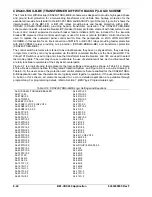
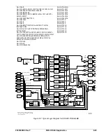
CDS240-BSBU-A-BE (Bus Protection with Backup) Logic Scheme
This logic scheme (CDS240-BSBU-A-BE) provides a primary zone of high-speed, low impedance, bus
differential protection and a backup zone of high-speed instantaneous overcurrent (bus interlocking)
protection. Feeder circuit backup protection and overall backup protection from the bus main to the first
down-line interrupting device for each feeder circuit are also provided.
The percent-restrained differential protection function is the only function of the 87 protection element
required for this application. Set the pickup of the 2
nd
, 5
th
, and 87 unrestrained functions to 0 (setting
disabled). The 87 unrestrained function has a setting only when the 2
nd
and 5
th
harmonic restraint
functions are set for transformer applications (refer to the discussion in
Overview of Preprogrammed
Logic Schemes
).
The 87 restrained element provides conventional high speed, low impedance, and bus differential
protection. On feeder circuits using the 851 or 951 distribution feeder protection relays, the 50T, P, and Q
elements from the BE1-CDS240 are hard wired to the feeder protection package, providing a high-speed
backup, bus interlocked, zone of bus protection. When the BE1-CDS240 detects a feeder relay out of
service, the BE1-CDS240 50/51P, N, and Q protection elements and outputs are automatically
reconfigured to provide feeder protection. The 150/151P, N, and Q protection elements of the BE1-
CDS240 are time coordinated with the bus and feeder circuit protection, providing overall backup
protection from the transformer side of the bus main breaker through the first down-line interrupting
device on the distribution circuit.
CDS240-MOTR-A-BE (Motor Protection) Logic Scheme
This logic scheme (CDS240-MOTR-A-BE) incorporates the essential differential and overcurrent
protection elements that are ideally suited for large motor protection. The 87 restrained element provides
high-speed differential fault protection. Sensitive instantaneous and time overcurrent, negative-sequence
elements, 50TQ and 51Q are incorporated for open phase and phase imbalance protection. High-speed
ground fault protection is accomplished with an instantaneous overcurrent element 50TN and the 51P
and 251P elements provide motor overload and stall (jam) protection. Further protection, locked rotor
protection and start/run detection for low and high inertia motors, is accomplished using a combination of
instantaneous and time overcurrent phase elements, virtual logic switches, and a speed sensing input
from the motor.
The percent-restrained differential protection function is the only function of the 87 protection element
required for this application. Set the pickup of the 2
nd
, 5
th
, and 87 unrestrained functions to 0 (setting
disabled). The 87 unrestrained function has a setting only when the 2
nd
and 5
th
harmonic restraint
functions are set for transformer applications (refer to the discussion in
Overview of Preprogrammed
Logic Schemes
).
DETAILS OF ADDITIONAL PREPROGRAMMED LOGIC SCHEMES
The following subsections describe each of the five additional logic library preprogrammed logic schemes
in detail. For each scheme, operation of the protection, and control logic under normal conditions is
described. The features of each logic scheme are broken down into functional groups and described in
detail.
Summary of Contents for BE1-CDS240
Page 2: ......
Page 8: ...vi BE1 CDS240 Introduction 9365200990 Rev F This page intentionally left blank ...
Page 38: ...1 28 BE1 CDS240 General Information 9365200990 Rev F This page intentionally left blank ...
Page 40: ...ii BE1 CDS240 Quick Start 9365200990 Rev F This page intentionally left blank ...
Page 152: ...ii BE1 CDS240 Metering 9365200990 Rev F This page intentionally left blank ...
Page 226: ...iv BE1 CDS240 Application 9365200990 Rev F This page intentionally left blank ...
Page 286: ...ii BE1 CDS240 Security 9365200990 Rev F This page intentionally left blank ...
Page 290: ...9 4 BE1 CDS240 Security 9365200990 Rev F This page intentionally left blank ...
Page 292: ...ii BE1 CDS240 Human Machine Interface 9365200990 Rev F This page intentionally left blank ...
Page 306: ...10 14 BE1 CDS240 Human Machine Interface 9365200990 Rev F This page intentionally left blank ...
Page 308: ...ii BE1 CDS240 ASCII Command Interface 9365200990 Rev F This page intentionally left blank ...
Page 342: ...11 34 BE1 CDS240 ASCII Command Interface 9365200990 Rev F This page intentionally left blank ...
Page 349: ...Figure 12 5 Horizontal Rack Mount Front View 9365200990 Rev F BE1 CDS240 Installation 12 5 ...
Page 361: ...Figure 12 17 Typical DC Connection Diagrams 9365200990 Rev F BE1 CDS240 Installation 12 17 ...
Page 372: ...12 28 BE1 CDS240 Installation 9365200990 Rev F This page intentionally left blank ...
Page 468: ...13 92 BE1 CDS240 Testing and Maintenance 9365200990 Rev F This page intentionally left blank ...
Page 512: ...14 42 BE1 CDS240 BESTCOMS Software 9365200990 Rev F This page intentionally left blank ...
Page 544: ...ii BE1 CDS240 Terminal Communication 9365200990 Rev F This page intentionally left blank ...
Page 550: ...ii BE1 CDS240 Settings Calculations 9365200990 Rev F This page intentionally left blank ...
Page 578: ...D 28 BE1 CDS240 Settings Calculations 9365200990 Rev F This page intentionally left blank ...
Page 579: ......


