8-48
BE1-CDS240 Application
9365200990 Rev F
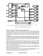
If high Inertia is selected, it is unblocked when starting as determined by intermediate logic VO7. Virtual
Control Switch 143 selects whether high inertia motor starting is determined by speed switch or by current
detection (50TP protection element set at 85% of locked rotor current).
In the CDS240-MOTR-A-BE scheme, the 50TP protection element is used for motor start detection (50S).
The 250TP protection element is used to detect when the motor is running. It supervises the 150TP
locked rotor protection for low inertia motor applications and the 251P jam or stall protection. Targets
should not be enabled with the SG-TARG setting for either the 50TP or the 250TP function.
Integration of Protection, Control, and I/O Elements
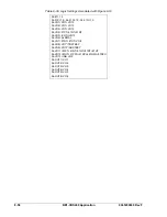
The logic settings in Table 8-31 also include the logic equations that establish the control connections or
logic wiring between elements of the CDS240-MOTR-A-BE scheme. For example, the two underlined
equations in the settings of Table 8-31 provide the electrical connection between the 87 element (trip
enabled by the settings) and trip output 1. Referring to Figures 8-13 and 8-14, all protection elements in
the CDS240-MOTR-A-BE scheme are enabled to trip. All protection elements, with the exception of
250TP start/run detection, are connected to trip through Output 1. Motor phase unbalance alarms are
connected through Output 5 and motor overload alarms through output 4. Protection elements set at 0
are setting disabled and will not provide a trip output even if logic enabled.
The 87, 50TN, 50TQ, 51P, and 251P protection elements provide primary and backup fault/open phase
protection including stall protection for a running motor. The remainder of the protection is associated with
starting the motor. High and low inertia locked rotor protection is provided by 150TP and 151P protection
elements. Start/run current detection for low inertia motors is provided by the 250TP protection element
and start detection for high inertia motors is provided by either speed switch input or current detection
from the 50TP protection element.
High Inertia Motor Start
As shown on Figure 8-13, the first thing the user must do is select the high inertia position of Virtual
Control Switch 243 and then select between motion detection by external speed switch or motion
detection by current sensing. This is accomplished by the position of Virtual Switch 143. If we assume
current sensing was selected, then, when the breaker is closed, 50TP picks up forcing VO7 high and
removing the block from 151P locked rotor protection. Locked rotor 151P picks up and starts timing. If the
motor current drops below the 50TP setting before 151P times out, the locked rotor protection is blocked
and the motor start was successful. However, if the motor current stays high until 151P times out, the
motor is tripped through Output 1 and the Major Alarm LED on the front panel lights.
If speed switch input is selected by the position of Virtual Switch 143, then, when the breaker is closed,
250TP picks up and a closed external speed sensing contact at Input 2 unblocks the locked rotor
protection. If the speed sensing contact opens, or the 250TP drops out, locked rotor protection is blocked
and the motor successfully starts.
For high or low inertia starts, 251P jam or stall protection is blocked by V08 until 250T drops out or times
out.
For high inertia motors, the distance between the burn-up curve and the knee point of the start/run plot is
typically close. Locked rotor protection will reset when the motor comes up to speed but abnormally high
run current could still be present but not high enough to trip on overload. If the abnormal run current is
allowed to persist, motor life will be shortened through accelerated thermal aging. To alert the user to this
condition, when 250TP has timed out and 51P is picked up, Virtual Output 14 is programmed to go high
which drives alarm bit #22 in the programmable alarm mask and alarms through Output 4 to the outside
world. It can also be masked to drive an alarm LED, and the alarm display to indicate when the overload
condition exists. If the overload is high enough to time out 51P, the breaker is tripped through Output 1.
Phase imbalance can lead to stator and rotor overheating resulting in the same scenario as previously
discussed. For this reason, a circuit similar to the overload alarm is included for phase imbalance. When
51Q picks up, Virtual Output 15 is programmed to go high which drives alarm bit #23 in the
programmable alarm mask and alarms through Output 5 to the outside world. It can also be masked to
drive an alarm LED and the alarm display to indicate when the imbalance condition exists. If the
imbalance is high enough to time out 51Q, the breaker is tripped through Output 1.
Low Inertia Motor Start
Selecting the low inertia protection through Virtual Control Switch 243 disables the 151P high inertia
locked rotor protection. When the breaker is closed, 250TP, start/run current detection and 150TP low
inertia locked rotor protection, start timing. If the motor comes up to speed before time out of the 150TP
Summary of Contents for BE1-CDS240
Page 2: ......
Page 8: ...vi BE1 CDS240 Introduction 9365200990 Rev F This page intentionally left blank ...
Page 38: ...1 28 BE1 CDS240 General Information 9365200990 Rev F This page intentionally left blank ...
Page 40: ...ii BE1 CDS240 Quick Start 9365200990 Rev F This page intentionally left blank ...
Page 152: ...ii BE1 CDS240 Metering 9365200990 Rev F This page intentionally left blank ...
Page 226: ...iv BE1 CDS240 Application 9365200990 Rev F This page intentionally left blank ...
Page 286: ...ii BE1 CDS240 Security 9365200990 Rev F This page intentionally left blank ...
Page 290: ...9 4 BE1 CDS240 Security 9365200990 Rev F This page intentionally left blank ...
Page 292: ...ii BE1 CDS240 Human Machine Interface 9365200990 Rev F This page intentionally left blank ...
Page 306: ...10 14 BE1 CDS240 Human Machine Interface 9365200990 Rev F This page intentionally left blank ...
Page 308: ...ii BE1 CDS240 ASCII Command Interface 9365200990 Rev F This page intentionally left blank ...
Page 342: ...11 34 BE1 CDS240 ASCII Command Interface 9365200990 Rev F This page intentionally left blank ...
Page 349: ...Figure 12 5 Horizontal Rack Mount Front View 9365200990 Rev F BE1 CDS240 Installation 12 5 ...
Page 361: ...Figure 12 17 Typical DC Connection Diagrams 9365200990 Rev F BE1 CDS240 Installation 12 17 ...
Page 372: ...12 28 BE1 CDS240 Installation 9365200990 Rev F This page intentionally left blank ...
Page 468: ...13 92 BE1 CDS240 Testing and Maintenance 9365200990 Rev F This page intentionally left blank ...
Page 512: ...14 42 BE1 CDS240 BESTCOMS Software 9365200990 Rev F This page intentionally left blank ...
Page 544: ...ii BE1 CDS240 Terminal Communication 9365200990 Rev F This page intentionally left blank ...
Page 550: ...ii BE1 CDS240 Settings Calculations 9365200990 Rev F This page intentionally left blank ...
Page 578: ...D 28 BE1 CDS240 Settings Calculations 9365200990 Rev F This page intentionally left blank ...
Page 579: ......


