SECTION 10
HUMAN-MACHINE INTERFACE
GENERAL
This section describes the BE1-CDS240 Current Differential System optional human-machine interface
(HMI) and illustrates the front panel display menu tree branches.
FRONT PANEL DISPLAY
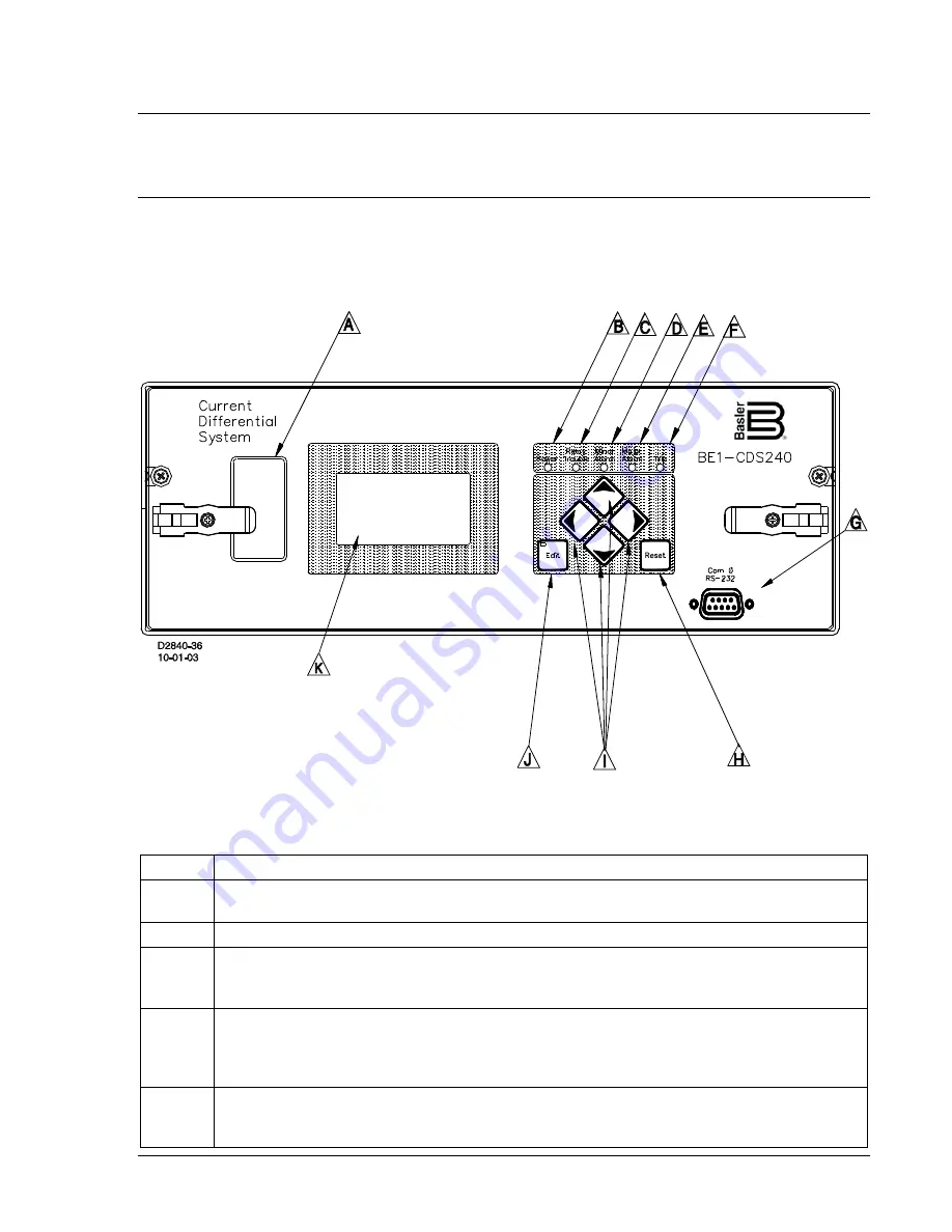
Figure 10-1 shows the optional front panel HMI for a horizontal mount BE1-CDS240 Current Differential
System. The vertical mount relay layout has identical functionality. The locators and descriptions of Table
10-1 correspond to the locators shown in Figure 10-1.
Figure 10-1. BE1-CDS240 Current Differential System with Optional HMI
Table 10-1. Front Panel HMI Descriptions
Locator Description
A
Identification Label
– This label lists the style number, serial number, sensing input current
and voltage range, and power supply input voltages.
B
Power Indicator
– This green LED lights when operating power is applied to the relay.
C
Relay Trouble Indicator
– This red LED lights momentarily during start-up and lights
continuously when a relay failure is detected. Section 6,
Reporting and Alarm Functions
,
provides a complete description of all relay failure alarm diagnostics.
D, E
Minor Alarm, Major Alarm Indicators
– These red LEDs light to indicate that a programmable
alarm has been set. Each indicator can be programmed to annunciate one or more
conditions. Section 6,
Reporting and Alarm Functions
, provides detailed information about
programming alarms.
F
Trip Indicator
– A flashing Trip LED indicates that a protective element is picked up. A
continuously lit LED indicates that a trip output is closed. This red LED is sealed in if a
protective trip has occurred and targets are displayed.
9365200990 Rev F
BE1-CDS240 Human-Machine Interface
10-1
Summary of Contents for BE1-CDS240
Page 2: ......
Page 8: ...vi BE1 CDS240 Introduction 9365200990 Rev F This page intentionally left blank ...
Page 38: ...1 28 BE1 CDS240 General Information 9365200990 Rev F This page intentionally left blank ...
Page 40: ...ii BE1 CDS240 Quick Start 9365200990 Rev F This page intentionally left blank ...
Page 152: ...ii BE1 CDS240 Metering 9365200990 Rev F This page intentionally left blank ...
Page 226: ...iv BE1 CDS240 Application 9365200990 Rev F This page intentionally left blank ...
Page 286: ...ii BE1 CDS240 Security 9365200990 Rev F This page intentionally left blank ...
Page 290: ...9 4 BE1 CDS240 Security 9365200990 Rev F This page intentionally left blank ...
Page 292: ...ii BE1 CDS240 Human Machine Interface 9365200990 Rev F This page intentionally left blank ...
Page 306: ...10 14 BE1 CDS240 Human Machine Interface 9365200990 Rev F This page intentionally left blank ...
Page 308: ...ii BE1 CDS240 ASCII Command Interface 9365200990 Rev F This page intentionally left blank ...
Page 342: ...11 34 BE1 CDS240 ASCII Command Interface 9365200990 Rev F This page intentionally left blank ...
Page 349: ...Figure 12 5 Horizontal Rack Mount Front View 9365200990 Rev F BE1 CDS240 Installation 12 5 ...
Page 361: ...Figure 12 17 Typical DC Connection Diagrams 9365200990 Rev F BE1 CDS240 Installation 12 17 ...
Page 372: ...12 28 BE1 CDS240 Installation 9365200990 Rev F This page intentionally left blank ...
Page 468: ...13 92 BE1 CDS240 Testing and Maintenance 9365200990 Rev F This page intentionally left blank ...
Page 512: ...14 42 BE1 CDS240 BESTCOMS Software 9365200990 Rev F This page intentionally left blank ...
Page 544: ...ii BE1 CDS240 Terminal Communication 9365200990 Rev F This page intentionally left blank ...
Page 550: ...ii BE1 CDS240 Settings Calculations 9365200990 Rev F This page intentionally left blank ...
Page 578: ...D 28 BE1 CDS240 Settings Calculations 9365200990 Rev F This page intentionally left blank ...
Page 579: ......


