


4. Once all of the settings on the screen have been entered, press the
Edit
pushbutton a second
time and the settings will be validated. If the settings are in range, the screen will flash
CHANGES SAVED
, and the Edit LED will go out. If you want to abort the edit session without
changing any settings, press the
Reset
pushbutton before you press the
Edit
pushbutton the
second time. The screen will flash
CHANGES LOST
and the Edit LED will go out.
Performing Control Operations
Control operations can be executed from the LCD HMI from menu branch 2,
CONTROL.
These functions
allow you to control the state of virtual switches, override logic and control the active setting group, and
override the logic and control the state of output contacts. All of these functions work similarly to the
process of entering settings in that you press the
Edit
pushbutton, use the
UP
and
DOWN
scroll
pushbuttons to select the desired state and press the
Edit
pushbutton for the action to be executed.
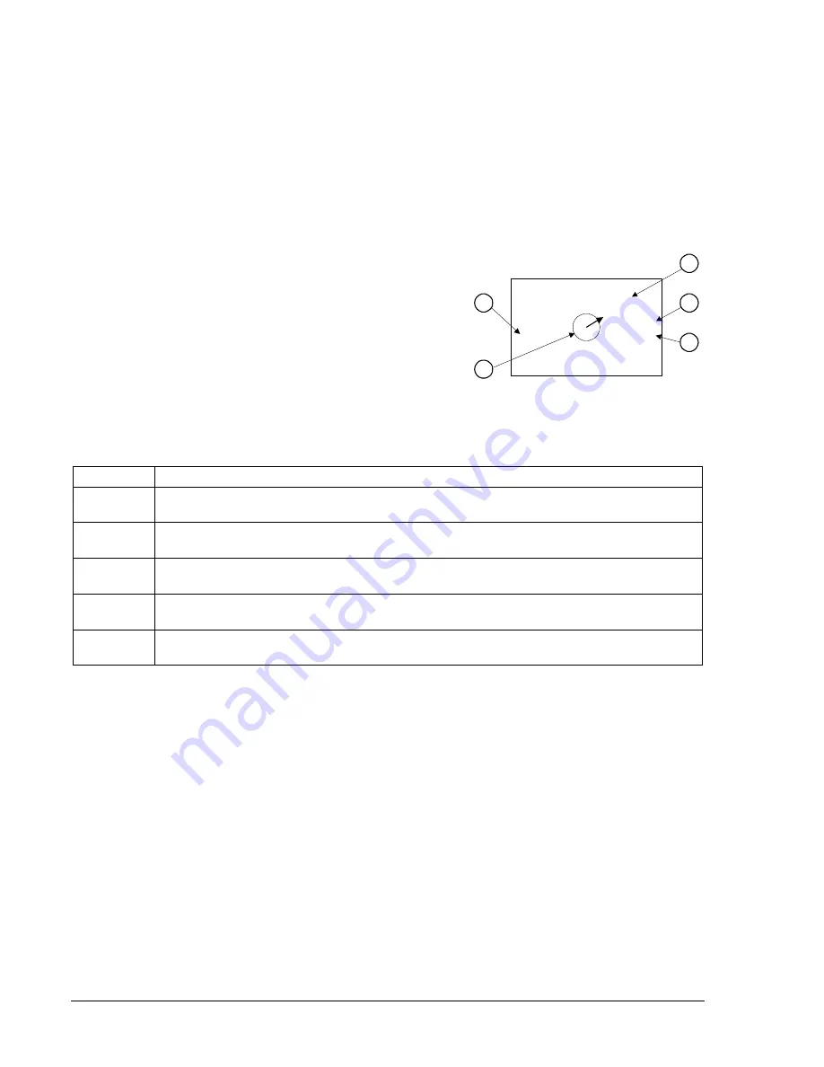
Figure 10-11 shows virtual switch 243 as an example of a virtual
switch screen. See Section 4,
Protection and Control,
for more
details on the x43 and 101 functions. Table 10-3 describes each
of the callouts shown on Figure 10-11. The user programmable
label for this switch has been set to DIFF_CUTOFF. The TRUE
(closed) state label has been set to NORMAL and the FALSE
(open) state label has been set to 87_OFF. The logical mode for
this application would be set to Mode 2 (On/Off switch).
\CTRL\43\243
DIFF_CUTOFF
ACTION
NORMAL
NORMAL
87_OFF
<143 >343
2.1.3
D2840-18.vsd
02-09-99
A
B
C
E
D
Figure 10-11. Virtual Control Switch 243
Table 10-3. Virtual Control Switches Controls and Indicators
Locator Description
A
User selectable label (meaningful name) for specific virtual switches. Switch 243
identification label set to DIFF_CUTOFF.
B
User selectable label for the closed (1) state for Virtual Switch 243. Switch 243 closed
state label set to NORMAL.
C
User selectable label for the open (0) state for Virtual Switch 243. Switch 243 open state
label set to 87_OFF.
D
Icon to show the current switch position (status). In Figure 10-11, the current status is the
closed state, which is labeled NORMAL.
E
Current switch status. This indicator should correspond to the current user labeled switch
status. The switch is closed (1) and the user label for closed is NORMAL.
To operate the switch, you would use the following procedure:
1. Using the manual scrolling pushbuttons, scroll to Screen 2.1.x, \CTRL\43\. Alternatively, if the
screen has been placed in the automatic scroll list, simply wait for it to appear and press the
RIGHT
or
LEFT
scroll pushbutton to freeze the display.
2. Press
the
Edit
pushbutton to gain access. If password security has been initiated for control
functions, you will be prompted to enter the appropriate password. See the following paragraphs,
Entering Passwords,
for details on entering passwords from the HMI. Once access has been
gained to the control function, the Edit LED will be lighted and a cursor will appear in the action
field.
3. Press
the
UP
or
DOWN
scrolling key to select the desired action. The selections available are
dependent upon the logic mode setting for that switch. If it is set to Mode 1, the action choices are
pulse or one of the two positions as defined by the user programmable state labels. If the mode is
set to Mode 2 (ON/OFF Switch), the choices for action are limited to one of the two positions. If
the mode is set to Mode 3 (OFF/Momentary ON Switch), the choice for action is limited to pulse.
4. Press
the
Edit
pushbutton a second time and the switch will change to the selected position, the
screen will flash
CHANGES SAVED
and the Edit LED will go out. If you want to abort the edit
session without changing any controls, press the
Reset
pushbutton before you press the
Edit
pushbutton the second time. The screen will flash
CHANGES LOST
and the Edit LED will go out.
10-12
BE1-CDS240 Human-Machine Interface
9365200990 Rev F
Summary of Contents for BE1-CDS240
Page 2: ......
Page 8: ...vi BE1 CDS240 Introduction 9365200990 Rev F This page intentionally left blank ...
Page 38: ...1 28 BE1 CDS240 General Information 9365200990 Rev F This page intentionally left blank ...
Page 40: ...ii BE1 CDS240 Quick Start 9365200990 Rev F This page intentionally left blank ...
Page 152: ...ii BE1 CDS240 Metering 9365200990 Rev F This page intentionally left blank ...
Page 226: ...iv BE1 CDS240 Application 9365200990 Rev F This page intentionally left blank ...
Page 286: ...ii BE1 CDS240 Security 9365200990 Rev F This page intentionally left blank ...
Page 290: ...9 4 BE1 CDS240 Security 9365200990 Rev F This page intentionally left blank ...
Page 292: ...ii BE1 CDS240 Human Machine Interface 9365200990 Rev F This page intentionally left blank ...
Page 306: ...10 14 BE1 CDS240 Human Machine Interface 9365200990 Rev F This page intentionally left blank ...
Page 308: ...ii BE1 CDS240 ASCII Command Interface 9365200990 Rev F This page intentionally left blank ...
Page 342: ...11 34 BE1 CDS240 ASCII Command Interface 9365200990 Rev F This page intentionally left blank ...
Page 349: ...Figure 12 5 Horizontal Rack Mount Front View 9365200990 Rev F BE1 CDS240 Installation 12 5 ...
Page 361: ...Figure 12 17 Typical DC Connection Diagrams 9365200990 Rev F BE1 CDS240 Installation 12 17 ...
Page 372: ...12 28 BE1 CDS240 Installation 9365200990 Rev F This page intentionally left blank ...
Page 468: ...13 92 BE1 CDS240 Testing and Maintenance 9365200990 Rev F This page intentionally left blank ...
Page 512: ...14 42 BE1 CDS240 BESTCOMS Software 9365200990 Rev F This page intentionally left blank ...
Page 544: ...ii BE1 CDS240 Terminal Communication 9365200990 Rev F This page intentionally left blank ...
Page 550: ...ii BE1 CDS240 Settings Calculations 9365200990 Rev F This page intentionally left blank ...
Page 578: ...D 28 BE1 CDS240 Settings Calculations 9365200990 Rev F This page intentionally left blank ...
Page 579: ......


