13-12
BE1-CDS240 Testing and Maintenance
9365200990 Rev F
That the fault reporting settings are properly set such that the relay properly indicates pickup and
trip states and records targets. These settings are set from the ASCII command interface using
the SG-TRIGGER and SG-TARG setting commands. See Section 6,
Reporting and Alarm
Functions, Fault Reporting Functions,
for more details.
Testing Phase Differential Protection with Internal Compensation
The internal phase and zero-sequence compensation features of the relay can combine the currents from
multiple CT input circuits and/or subtract out the zero-sequence components before their use by the
phase differential function. Thus, the testing of this function with the internal compensation features can
be somewhat complicated. For this reason, a detailed test procedure is provided for verifying the set
points of this function with internal compensation. See Sidebar 13-1 in this section for more information
on how the internal compensation features work.
The CDS240 is a four winding differential relay. Testing the complete 87T scheme would require 12
controllable current sources. For simplicity, testing will be performed by evaluating sequential pairs of
input circuits (Inputs 1 verses Inputs 2, Inputs 2 verses Inputs 3, etc). This will confirm proper operation of
the complete scheme. The complete set of Input Circuit “pairs” is: CT1-CT2, CT1-CT3, CT1-CT4, CT2-
CT3, CT2-CT4, and CT3-CT4.
Step 1:
Record settings for the following tests:
The settings for the following tests should be recorded before starting the test. You will refer to these
settings throughout the test procedure.
Angle Compensation and Ground Source
compensation can be determined by matching the SG-
CTP(1,2,3, or 4) settings or Screen 6.3.1.1 with Table 3-3 in Section 3 and reading the right two
columns to determine what angle compensation is applied.
Tap Compensation
settings in each setting group can be determined from Screens 5.x.1.2 or
5.x.1.3 on the HMI. Or, check the S#-TAP87 settings from the ASCII command interface if
manual tap adjust is used. If automatic tap adjust is used, it will be necessary to use the settings
and Equations 4-1 and 4-2 from Section 4,
Protection and Control Functions, Differential
Protection
. BESTCOMS can also be used to change settings. See Section 14,
BESTCOMS
Software
.
Restrained Minimum Pickup, Slope,
and Unrestrained Pickup
settings can be determined from
Screens 5.x.1.1 on the HMI. Or, use the S#-87 settings from the ASCII command interface.
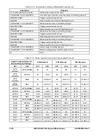
Alternatively, all of these parameters can be determined from reading the Current Check Record provided
by the Differential Alarm Function. To use this method, use the commands in Table 13-10.
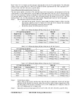
Table 13-11 lists the currents that will be seen by each 87 phase differential element after phase and
zero-sequence compensation. This table is based upon the internal compensation chart in Section 3,
Input and Output Functions, Input Current
. Examination of this table shows that for most cases, test
current injection using only one or two current sources will result in currents being applied to more than
one 87 phase element. See Sidebar 13-1 for more information on testing and compensated currents. The
following test procedures will enable you to determine the test points and which phases will be tested.
Summary of Contents for BE1-CDS240
Page 2: ......
Page 8: ...vi BE1 CDS240 Introduction 9365200990 Rev F This page intentionally left blank ...
Page 38: ...1 28 BE1 CDS240 General Information 9365200990 Rev F This page intentionally left blank ...
Page 40: ...ii BE1 CDS240 Quick Start 9365200990 Rev F This page intentionally left blank ...
Page 152: ...ii BE1 CDS240 Metering 9365200990 Rev F This page intentionally left blank ...
Page 226: ...iv BE1 CDS240 Application 9365200990 Rev F This page intentionally left blank ...
Page 286: ...ii BE1 CDS240 Security 9365200990 Rev F This page intentionally left blank ...
Page 290: ...9 4 BE1 CDS240 Security 9365200990 Rev F This page intentionally left blank ...
Page 292: ...ii BE1 CDS240 Human Machine Interface 9365200990 Rev F This page intentionally left blank ...
Page 306: ...10 14 BE1 CDS240 Human Machine Interface 9365200990 Rev F This page intentionally left blank ...
Page 308: ...ii BE1 CDS240 ASCII Command Interface 9365200990 Rev F This page intentionally left blank ...
Page 342: ...11 34 BE1 CDS240 ASCII Command Interface 9365200990 Rev F This page intentionally left blank ...
Page 349: ...Figure 12 5 Horizontal Rack Mount Front View 9365200990 Rev F BE1 CDS240 Installation 12 5 ...
Page 361: ...Figure 12 17 Typical DC Connection Diagrams 9365200990 Rev F BE1 CDS240 Installation 12 17 ...
Page 372: ...12 28 BE1 CDS240 Installation 9365200990 Rev F This page intentionally left blank ...
Page 468: ...13 92 BE1 CDS240 Testing and Maintenance 9365200990 Rev F This page intentionally left blank ...
Page 512: ...14 42 BE1 CDS240 BESTCOMS Software 9365200990 Rev F This page intentionally left blank ...
Page 544: ...ii BE1 CDS240 Terminal Communication 9365200990 Rev F This page intentionally left blank ...
Page 550: ...ii BE1 CDS240 Settings Calculations 9365200990 Rev F This page intentionally left blank ...
Page 578: ...D 28 BE1 CDS240 Settings Calculations 9365200990 Rev F This page intentionally left blank ...
Page 579: ......

