9365200990 Rev F
BE1-CDS240 Quick Start
2-1
SECTION 2
QUICK START
GENERAL
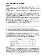
This section provides an overview of the BE1-CDS240 Current Differential System. You should be familiar
with the concepts behind the user interfaces and BESTlogic before you begin reading about the detailed
BE1-CDS240 functions. Sections 3 through 6 in this manual describe in detail each function of the BE1-
CDS240.
The following information is intended to provide the reader with a basic understanding of the three user
interfaces (front panel human-machine interface (HMI), ASCII serial communications link, and the
BESTCOMS for BE1-CDS240 software) and the security features provided in the BE1-CDS240 relay.
Detailed information on the operation of the HMI (human-machine interface) is in Section 10, and the
information on ASCII command communications is in Section 11. BESTCOMS is a Windows
based
software application (graphical user interface) that enhances communication between the PC user and
the BE1-CDS240 relay. BESTCOMS for the BE1-CDS240 is provided free of charge with the BE1-
CDS240 and details are provided in Section 14.
Also covered in this section is an overview of BESTlogic. BESTlogic is a highly flexible programmable
logic system that allows the user to apply the available functions with complete flexibility and customize
the system to meet the requirements of the protected power system. Detailed information on using
BESTlogic to design complete protection and control schemes for the protected circuit can be found in
Section 7,
BESTlogic Programmable Logic
, and Section 8,
Application
.
Sections 3 through 6 describe each function provided in the BE1-CDS240 relay and include references to
the following items. Note that not all items are appropriate for each function.
Human-machine interface (HMI) screens for setting the operational parameters.
BESTCOMS for setting the operational parameters.
BESTCOMS for setting up the BESTlogic required for functions in your protection and control
scheme.
Outputs from the function such as alarm and BESTlogic variables or data reports.
HMI screens for operation or interrogation of the outputs and reports provided by each function.
ASCII commands for operation or interrogation of the outputs and reports provided by each function.
About This Manual
The various application functions provided by this multifunction relay are divided into four functional
categories: input/output functions, protection and control functions, metering functions, and reporting and
alarm functions. Detailed descriptions of each individual function, setup, and use are covered in the
Sections as shown in Table 2-1. Detailed information on using programmable logic to create your
protection and control scheme is described in Section 7,
BESTlogic Programmable Logic
.
Table 2-1. Function Categories and Manual Sections Cross-Reference
Section Title
Section
Input and Output Functions
3
Protection and Control
4
Metering 5
Reporting and Alarm Functions
6
BESTlogic Programmable Logic
7
Application 8
BESTLOGIC
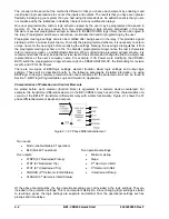
Each of the protection and control elements in the BE1-CDS240 is implemented as an independent
function that is equivalent to a single function, discrete device counterpart. Each independent element
has all of the inputs and outputs that the discrete component counterpart might have. Programming
BESTlogic is equivalent to choosing the devices required by your protection and control scheme and
drawing schematic diagrams to connect the inputs and outputs to obtain the desired operational logic.
Summary of Contents for BE1-CDS240
Page 2: ......
Page 8: ...vi BE1 CDS240 Introduction 9365200990 Rev F This page intentionally left blank ...
Page 38: ...1 28 BE1 CDS240 General Information 9365200990 Rev F This page intentionally left blank ...
Page 40: ...ii BE1 CDS240 Quick Start 9365200990 Rev F This page intentionally left blank ...
Page 152: ...ii BE1 CDS240 Metering 9365200990 Rev F This page intentionally left blank ...
Page 226: ...iv BE1 CDS240 Application 9365200990 Rev F This page intentionally left blank ...
Page 286: ...ii BE1 CDS240 Security 9365200990 Rev F This page intentionally left blank ...
Page 290: ...9 4 BE1 CDS240 Security 9365200990 Rev F This page intentionally left blank ...
Page 292: ...ii BE1 CDS240 Human Machine Interface 9365200990 Rev F This page intentionally left blank ...
Page 306: ...10 14 BE1 CDS240 Human Machine Interface 9365200990 Rev F This page intentionally left blank ...
Page 308: ...ii BE1 CDS240 ASCII Command Interface 9365200990 Rev F This page intentionally left blank ...
Page 342: ...11 34 BE1 CDS240 ASCII Command Interface 9365200990 Rev F This page intentionally left blank ...
Page 349: ...Figure 12 5 Horizontal Rack Mount Front View 9365200990 Rev F BE1 CDS240 Installation 12 5 ...
Page 361: ...Figure 12 17 Typical DC Connection Diagrams 9365200990 Rev F BE1 CDS240 Installation 12 17 ...
Page 372: ...12 28 BE1 CDS240 Installation 9365200990 Rev F This page intentionally left blank ...
Page 468: ...13 92 BE1 CDS240 Testing and Maintenance 9365200990 Rev F This page intentionally left blank ...
Page 512: ...14 42 BE1 CDS240 BESTCOMS Software 9365200990 Rev F This page intentionally left blank ...
Page 544: ...ii BE1 CDS240 Terminal Communication 9365200990 Rev F This page intentionally left blank ...
Page 550: ...ii BE1 CDS240 Settings Calculations 9365200990 Rev F This page intentionally left blank ...
Page 578: ...D 28 BE1 CDS240 Settings Calculations 9365200990 Rev F This page intentionally left blank ...
Page 579: ......

