


Second Harmonic Restraint Verification
Purpose:
To verify the operation of the 2
nd
harmonic restraint function of the 87 element.
Reference Commands:
SL-87, S(n)-87, S(n)-TAP87, SL-VO, SG-CT.
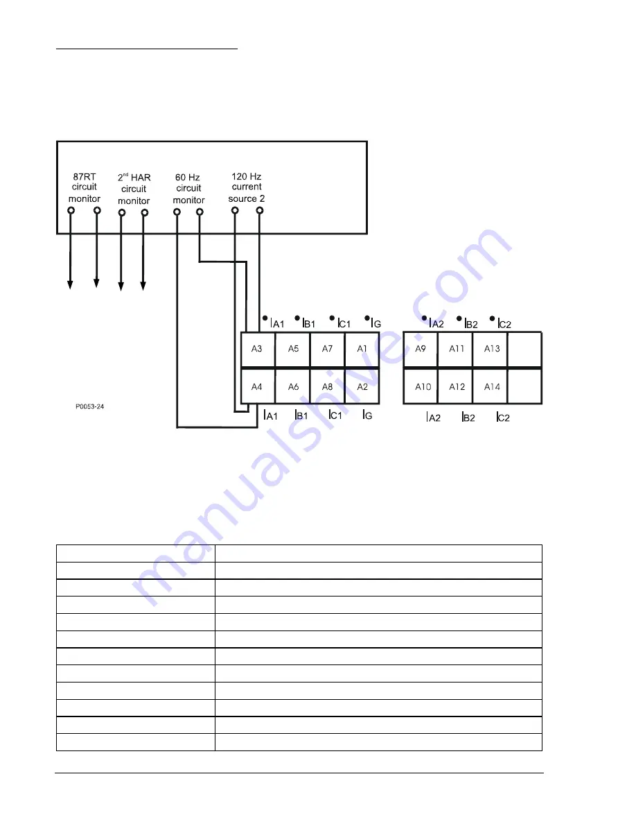
Step 1:
Parallel a 60 Hz current source and a second 120 Hz current source to Terminals A3, A4
(A-phase, Input 1). Refer to Figure 13-16.
An ohmmeter or continuity tester may be used to monitor output contact status.
Figure 13-16. Connection for Harmonic Restraint Verification
(Only Inputs 1 and 2 are shown for simplicity)
Step 2:
Send the commands listed in Table 13-34 to the relay to setup a test of the pickup of the
second harmonic restraint elements.
Table 13-34. Second Harmonic Restraint Elements Setup Commands
Command Purpose
A= Gain
access.
SL-N=NONE
Zero out custom logic settings/overwrite with logic = None settings.
Y Confirm
overwrite.
SL-N=2HAR
Sets 2HAR as custom logic name.
SL-87=1,0 Enables
87.
SL-VO1=87RT
Enables OUT1 to close with 87 restrained trip.
SG-CT2=1,WYE,NA,0
Ctr = 1, ct = wye, xfmr = na, no ground source.
SG-CT3=1,WYE,NA,0
Ctr = 1, ct = wye, xfmr = na, no ground source.
SG-CT4=1,WYE,NA,0
Ctr = 1, ct = wye, xfmr = na, no ground source.
SG-TRIGGER=87RT,87RPU,0
Enable 87RT to log and trigger fault recording.
S#-TAP87=MANUAL,2.00,3.80
set Tap 1 = 2.00 and Tap 2 = 3.80.
13-48
BE1-CDS240 Testing and Maintenance
9365200990 Rev F
Summary of Contents for BE1-CDS240
Page 2: ......
Page 8: ...vi BE1 CDS240 Introduction 9365200990 Rev F This page intentionally left blank ...
Page 38: ...1 28 BE1 CDS240 General Information 9365200990 Rev F This page intentionally left blank ...
Page 40: ...ii BE1 CDS240 Quick Start 9365200990 Rev F This page intentionally left blank ...
Page 152: ...ii BE1 CDS240 Metering 9365200990 Rev F This page intentionally left blank ...
Page 226: ...iv BE1 CDS240 Application 9365200990 Rev F This page intentionally left blank ...
Page 286: ...ii BE1 CDS240 Security 9365200990 Rev F This page intentionally left blank ...
Page 290: ...9 4 BE1 CDS240 Security 9365200990 Rev F This page intentionally left blank ...
Page 292: ...ii BE1 CDS240 Human Machine Interface 9365200990 Rev F This page intentionally left blank ...
Page 306: ...10 14 BE1 CDS240 Human Machine Interface 9365200990 Rev F This page intentionally left blank ...
Page 308: ...ii BE1 CDS240 ASCII Command Interface 9365200990 Rev F This page intentionally left blank ...
Page 342: ...11 34 BE1 CDS240 ASCII Command Interface 9365200990 Rev F This page intentionally left blank ...
Page 349: ...Figure 12 5 Horizontal Rack Mount Front View 9365200990 Rev F BE1 CDS240 Installation 12 5 ...
Page 361: ...Figure 12 17 Typical DC Connection Diagrams 9365200990 Rev F BE1 CDS240 Installation 12 17 ...
Page 372: ...12 28 BE1 CDS240 Installation 9365200990 Rev F This page intentionally left blank ...
Page 468: ...13 92 BE1 CDS240 Testing and Maintenance 9365200990 Rev F This page intentionally left blank ...
Page 512: ...14 42 BE1 CDS240 BESTCOMS Software 9365200990 Rev F This page intentionally left blank ...
Page 544: ...ii BE1 CDS240 Terminal Communication 9365200990 Rev F This page intentionally left blank ...
Page 550: ...ii BE1 CDS240 Settings Calculations 9365200990 Rev F This page intentionally left blank ...
Page 578: ...D 28 BE1 CDS240 Settings Calculations 9365200990 Rev F This page intentionally left blank ...
Page 579: ......


