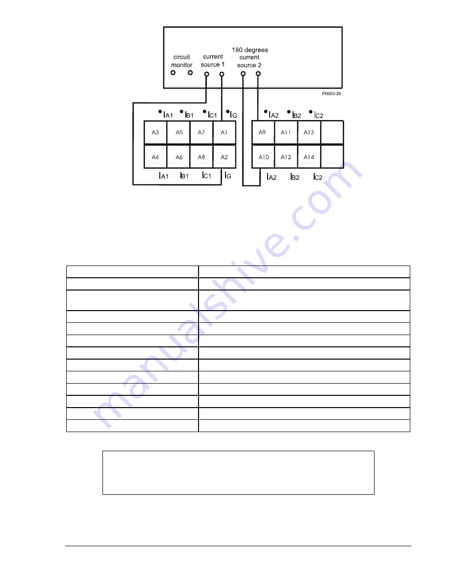
Figure 13-18. Connection for 87ND Restraint Pickup Verification
(Only Inputs 1 & 2 are shown for simplicity)
Step 2:
To prepare the x87ND element for testing the restraint operation accuracy, transmit the
commands in Table 13-42 to the relay.
Table 13-42. 87ND Restraint Operation Accuracy Test Commands
Command Purpose
A= Gain
access.
SL-N=NONE
Zero out custom logic settings/overwrite with logic = None
settings.
Y Confirm
overwrite.
SL-N=NDIFF
Name custom logic for this test.
SL-87=0 Disables
87.
SL-x87ND=2,0
Enables x87ND, mode = IG v. CT2, no blk.
SL-VO1=x87NDT
Enables OUT1 to close for 87ND restrained trip.
SG-CT2=1,WYE,NA,0 Input
2
ctr = 1, ct = wye, xfmr = na, no grd source
SG-TRIGGER=x87NDT, x87NDPU,0
Enable 87NDT to log and trigger fault recording.
S#-x87ND=0.35,15,50m
Minpu = 0.35, slope = 15%, minimum time delay.
E Exit.
Y Save
settings.
NOTE
The ground differential function always uses the maximum restraint principle as
its operating characteristic. Thus, the slope setting is simply a number between
15 and 60.
Step 3:
The auto tap compensation logic of the relay will calculate TAPN and TAPG values based on
CT ratios for the designated phase CTs and the ground CT. Since CTR2 and CTRG are both
equal to 1:1 for this test, the TAPN and TAPG values are both equal to the minimum settings
for either 5 ampere or 1-ampere relays (2.0 and 0.4 respectively).
9365200990 Rev F
BE1-CDS240 Testing and Maintenance
13-55
Summary of Contents for BE1-CDS240
Page 2: ......
Page 8: ...vi BE1 CDS240 Introduction 9365200990 Rev F This page intentionally left blank ...
Page 38: ...1 28 BE1 CDS240 General Information 9365200990 Rev F This page intentionally left blank ...
Page 40: ...ii BE1 CDS240 Quick Start 9365200990 Rev F This page intentionally left blank ...
Page 152: ...ii BE1 CDS240 Metering 9365200990 Rev F This page intentionally left blank ...
Page 226: ...iv BE1 CDS240 Application 9365200990 Rev F This page intentionally left blank ...
Page 286: ...ii BE1 CDS240 Security 9365200990 Rev F This page intentionally left blank ...
Page 290: ...9 4 BE1 CDS240 Security 9365200990 Rev F This page intentionally left blank ...
Page 292: ...ii BE1 CDS240 Human Machine Interface 9365200990 Rev F This page intentionally left blank ...
Page 306: ...10 14 BE1 CDS240 Human Machine Interface 9365200990 Rev F This page intentionally left blank ...
Page 308: ...ii BE1 CDS240 ASCII Command Interface 9365200990 Rev F This page intentionally left blank ...
Page 342: ...11 34 BE1 CDS240 ASCII Command Interface 9365200990 Rev F This page intentionally left blank ...
Page 349: ...Figure 12 5 Horizontal Rack Mount Front View 9365200990 Rev F BE1 CDS240 Installation 12 5 ...
Page 361: ...Figure 12 17 Typical DC Connection Diagrams 9365200990 Rev F BE1 CDS240 Installation 12 17 ...
Page 372: ...12 28 BE1 CDS240 Installation 9365200990 Rev F This page intentionally left blank ...
Page 468: ...13 92 BE1 CDS240 Testing and Maintenance 9365200990 Rev F This page intentionally left blank ...
Page 512: ...14 42 BE1 CDS240 BESTCOMS Software 9365200990 Rev F This page intentionally left blank ...
Page 544: ...ii BE1 CDS240 Terminal Communication 9365200990 Rev F This page intentionally left blank ...
Page 550: ...ii BE1 CDS240 Settings Calculations 9365200990 Rev F This page intentionally left blank ...
Page 578: ...D 28 BE1 CDS240 Settings Calculations 9365200990 Rev F This page intentionally left blank ...
Page 579: ......


