


Step 4:
Slowly ramp up current on the phase A input until OUT1, OUT2, and OUT3 close. Verify that
pickup occurred within the specified accuracy of the relay as listed in Table 13-52.
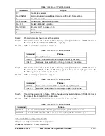
Table 13-52. Time Overcurrent 51 Element Accuracy
Sensing Type
Pickup Accuracy - Phase and Neutral
A or B (1 ampere nominal systems)
2% of setting or 10 milliamperes
D, E, or F (5 ampere nominal systems)
2% of setting or 50 milliamperes
Step 5: After pickup occurs, slowly ramp the current down until OUT1, OUT2 and OUT3 open. Verify
that dropout occurred as specified (95%
2%).
Step 6:
Repeat Steps 3, 4, and 5 for all values in Table 13-46. Optionally, reconnect the current
source to B-phase (A5*, A6) and C-phase (A7*, A8) inputs to test the response of all phases
for each succeeding test.
Step 7:
(Optional.) Repeat Steps 3 through 6 for phases B and C of the relay unless each phase was
tested in Step 4. If so, skip this step and proceed to Step 8.
Step 8:
(Optional.) Repeat Steps 1 through 7 for the 151/251/351/451 elements. Use Table 13-53 or
13-54 as a reference for substituting the commands used in Step 1.
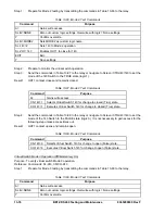
Table 13-53. Time Overcurrent 151 Element Test Logic
Replace These Commands
With These Commands For 151 Element Tests
SL-51=1,0 SL-151=1,0
SL-VO1=51PT SL-VO1=151PT
SL-VO2=51NT SL-VO2=151NT
SL-VO3=51QT SL-VO3=151QT
SG-TARG=51
SG-TARG=151
SG-TRIGGER=51PT+51NT+51QT, 51PPU+
51NPU,+51QPU,0
SG-TRIGGER=151PT+151NT+151QT,
151QTPU,0
Table 13-54. Time Overcurrent 251/351/451 Element Test Logic
Replace These Commands
With These Commands For x51 Element Tests
(where x=2,3,4)
SL-51=1,0 SL-x51=1,0
SL-VO1=51PT SL-VO1=x51PT
SL-VO2=51NT SL-VO2=x51NT
SL-VO3=51QT SL-VO3=x51QT
SG-TARG=51
SG-TARG=x51
SG-TRIGGER=51PT+51NT+51QT, 51PPU+
51NPU,+51QPU,0
SG-TRIGGER=x51PT+x51NT+x51QT,
x51QTPU,0
Step 9:
(Optional.) Repeat Steps 1 through 8 for the 51, 151, 251, 351, and 451 elements in Setting
Groups 1, 2 and 3. Use the following information as a guide to program the 1/151/251/351/451
elements in higher order setting groups.
In order to program the pickup of the elements in a higher order-setting group, you would
replace the
0
in the S
0
-51P, S
0
-51N, and S
0
-51Q commands in Table 13-45 with a 1, 2, or 3
for Setting Groups 1, 2, or 3. With the HMI, you can program each set of values by navigating
to the appropriate setting group Screen \PROT\SGn\51\51, where n is equal to the setting
group you desire. Refer to the CS/CO-GROUP command in Section 4,
Protection and Control
Functions,
for more information on changing the active setting group.
9365200990 Rev F
BE1-CDS240 Testing and Maintenance
13-61
Summary of Contents for BE1-CDS240
Page 2: ......
Page 8: ...vi BE1 CDS240 Introduction 9365200990 Rev F This page intentionally left blank ...
Page 38: ...1 28 BE1 CDS240 General Information 9365200990 Rev F This page intentionally left blank ...
Page 40: ...ii BE1 CDS240 Quick Start 9365200990 Rev F This page intentionally left blank ...
Page 152: ...ii BE1 CDS240 Metering 9365200990 Rev F This page intentionally left blank ...
Page 226: ...iv BE1 CDS240 Application 9365200990 Rev F This page intentionally left blank ...
Page 286: ...ii BE1 CDS240 Security 9365200990 Rev F This page intentionally left blank ...
Page 290: ...9 4 BE1 CDS240 Security 9365200990 Rev F This page intentionally left blank ...
Page 292: ...ii BE1 CDS240 Human Machine Interface 9365200990 Rev F This page intentionally left blank ...
Page 306: ...10 14 BE1 CDS240 Human Machine Interface 9365200990 Rev F This page intentionally left blank ...
Page 308: ...ii BE1 CDS240 ASCII Command Interface 9365200990 Rev F This page intentionally left blank ...
Page 342: ...11 34 BE1 CDS240 ASCII Command Interface 9365200990 Rev F This page intentionally left blank ...
Page 349: ...Figure 12 5 Horizontal Rack Mount Front View 9365200990 Rev F BE1 CDS240 Installation 12 5 ...
Page 361: ...Figure 12 17 Typical DC Connection Diagrams 9365200990 Rev F BE1 CDS240 Installation 12 17 ...
Page 372: ...12 28 BE1 CDS240 Installation 9365200990 Rev F This page intentionally left blank ...
Page 468: ...13 92 BE1 CDS240 Testing and Maintenance 9365200990 Rev F This page intentionally left blank ...
Page 512: ...14 42 BE1 CDS240 BESTCOMS Software 9365200990 Rev F This page intentionally left blank ...
Page 544: ...ii BE1 CDS240 Terminal Communication 9365200990 Rev F This page intentionally left blank ...
Page 550: ...ii BE1 CDS240 Settings Calculations 9365200990 Rev F This page intentionally left blank ...
Page 578: ...D 28 BE1 CDS240 Settings Calculations 9365200990 Rev F This page intentionally left blank ...
Page 579: ......


