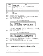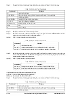
Step 5:
After each pickup occurs, slowly ramp current down until OUT1, OUT2, and OUT3 open.
Dropout should occur at 95%
2%.
Table 13-57. Time Overcurrent 51 Element Test Values
Relay Trip
Sensing Input Type
Time Dial
Applied Current
Lower Limit
Higher Limit
1.50 A
0.748 sec
0.827 sec
0.5
5.00 A
0.190 sec
0.240 sec
1.50 A
7.244 sec
8.007 sec
5.0
5.00 A
1.798 sec
1.988 sec
1.50 A
14.318 sec
15.825 sec
1 A
9.9
5.00 A
3.535 sec
3.907 sec
7.5 A
0.748 sec
0.827 sec
0.5
25.0 A
0.190 sec
0.240 sec
7.5 A
7.244 sec
8.007 sec
5.0
25.0 A
1.798 sec
1.988 sec
7.5 A
14.318 sec
15.825 sec
5 A
9.9
25.0 A
3.535 sec
3.907 sec
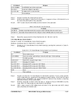
Step 6:
Repeat Steps 3, 4 and 5 for all current and time dial settings listed (using the command S0-
51P, 51N, and 51Q or by navigating to Screen \PROT\SG0\51\51 to edit the 51P, 51N, and
51Q settings) and, optionally, reconnect the current source to B-phase (A5, A6) and C-phase
(A7, A8) inputs to test the response of all phases for each succeeding test.
Step 7:
(Optional.) Repeat Steps 2 through 6 for B and C phase elements unless each phase was
tested in previous steps. If so, skip this step and proceed to Step 8.
Step 8:
(Optional.) Repeat Steps 1 through 7 for the 151, 251, 351, and 451 elements respectively.
Use Table 13-51 or 13-52 as a reference for substituting the commands used in Step 1.
Step 9:
(Optional.) Repeat Steps 1 through 8 for the 51, 151, 251, 351, and 451 elements in Setting
Groups 1, 2, and 3. Use the following information as a guide to program the
51/151/251/351/451 elements in higher order setting groups.
In order to program the pickup of the elements in a higher order-setting group, you would
replace the
0
in the S
0
-51P, S
0
-51N, and S
0
-51Q commands in Table 13-50 with either a 1, 2
or 3 for Setting Groups 1, 2 or 3. Or, you can program each set of values by navigating to the
appropriate setting group Screen \PROT\SGn\51\51 where n is equal to the setting group you
desire. Refer to the CS/CO-GROUP command in Section 4,
Protection and Control Functions,
for more information on changing the active setting group.
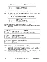
To change from Setting Group 0 to Setting Group 1, execute the following commands:
CS-GROUP=1 Select Setting Group 1
CO-GROUP=1 Execute Setting Group 1
Using the basic information in Table 13-50, program the pickup of the elements for Setting
Group 1 and, optionally, proceed with the testing.
Volts per Hertz Overexcitation (24)
Purpose:
To verify the operating accuracy of the 24 protection element.
Reference Commands:
SL-24, SL-VO, SL-GROUP, RG-STAT
Overexcitation, Volts/Hertz Alarm, Integrating Time and Definite Time Pickup Verification
The BE1-CDS240 detects overexcitation conditions with a volts/hertz element that consist of one alarm
setting, one integrating time characteristic with selectable exponents (3 sets of time curves as shown in
9365200990 Rev F
BE1-CDS240 Testing and Maintenance
13-63
Summary of Contents for BE1-CDS240
Page 2: ......
Page 8: ...vi BE1 CDS240 Introduction 9365200990 Rev F This page intentionally left blank ...
Page 38: ...1 28 BE1 CDS240 General Information 9365200990 Rev F This page intentionally left blank ...
Page 40: ...ii BE1 CDS240 Quick Start 9365200990 Rev F This page intentionally left blank ...
Page 152: ...ii BE1 CDS240 Metering 9365200990 Rev F This page intentionally left blank ...
Page 226: ...iv BE1 CDS240 Application 9365200990 Rev F This page intentionally left blank ...
Page 286: ...ii BE1 CDS240 Security 9365200990 Rev F This page intentionally left blank ...
Page 290: ...9 4 BE1 CDS240 Security 9365200990 Rev F This page intentionally left blank ...
Page 292: ...ii BE1 CDS240 Human Machine Interface 9365200990 Rev F This page intentionally left blank ...
Page 306: ...10 14 BE1 CDS240 Human Machine Interface 9365200990 Rev F This page intentionally left blank ...
Page 308: ...ii BE1 CDS240 ASCII Command Interface 9365200990 Rev F This page intentionally left blank ...
Page 342: ...11 34 BE1 CDS240 ASCII Command Interface 9365200990 Rev F This page intentionally left blank ...
Page 349: ...Figure 12 5 Horizontal Rack Mount Front View 9365200990 Rev F BE1 CDS240 Installation 12 5 ...
Page 361: ...Figure 12 17 Typical DC Connection Diagrams 9365200990 Rev F BE1 CDS240 Installation 12 17 ...
Page 372: ...12 28 BE1 CDS240 Installation 9365200990 Rev F This page intentionally left blank ...
Page 468: ...13 92 BE1 CDS240 Testing and Maintenance 9365200990 Rev F This page intentionally left blank ...
Page 512: ...14 42 BE1 CDS240 BESTCOMS Software 9365200990 Rev F This page intentionally left blank ...
Page 544: ...ii BE1 CDS240 Terminal Communication 9365200990 Rev F This page intentionally left blank ...
Page 550: ...ii BE1 CDS240 Settings Calculations 9365200990 Rev F This page intentionally left blank ...
Page 578: ...D 28 BE1 CDS240 Settings Calculations 9365200990 Rev F This page intentionally left blank ...
Page 579: ......


