
13-64
BE1-CDS240 Testing and Maintenance
9365200990 Rev F
Appendix C,
Overexcitation (24) Inverse Time Curves)
and two definite time characteristics. Note that
V/Hz nominal is 69.3 volts (phase to neutral) x square root 3/60 Hz, or 2.001. That is, at nominal voltage
and frequency (60 Hz system) 1 pu V/Hz = 2.001.
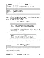
Step 1:
Prepare the 24 pickup function for testing by transmitting the commands in Table 13-58 to the
relay. Reset targets.
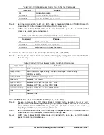
Table 13-58. V/Hz Alarm, Integrating Time, and Definite Time Test Commands
Command
Purpose
A=
Gain write access
SL-N=NONE
Zero out custom logic settings
Overwrite with logic = None settings
Y Confirm
overwrite
SL-N=24
Sets 24 as custom logic name
SG-VTP=1,4W,PN,PN
Set VT phase voltage parameters
SG-NOM=69.3,5.00
Set nominal voltage to 69.3 P to N
SA-MAJ=31
Enables Major Alarm Light for 24 alarm
SL-24=1,0
Enables 24, disables blocking
SG-TRIG=24T, 24PU, 0
Enables 24 to log and trigger fault recording
EXIT;Y
Exit and save settings
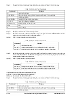
Step 2:
Using Table 13-59 as a guide, transmit the setting commands to the relay.
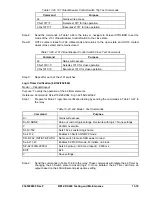
Table 13-59. Alarm, Integrating Time, and Definite Time Pickup Settings (Step 2)
Command
Purpose
SA-24=2.05,0.0
Set 24 Alarm at 1.025% of nominal (2.05V/Hz) and time delay = 0.
S0-24=2.1,0.0,0.0,2.0
Set 24 Integrating PU at 1.05% of nominal (2.10 V/Hz), Trip Time Dial = 0,
Reset Time Dial = 0, time curve exponent = 2.
S0-24D=0.0,50ms,0.0,
50ms
Sets 24 definite pickups at 0 and time definite time delay at minimum.
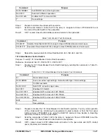
Step 3: Prepare to monitor the operation of the 24 Alarm and Trip functions. Alarm operation can be
verified by monitoring the Major Alarm LED on the relay's front panel. Operation of 24T by can
be verified by monitoring OUT1.
Step 4: Connect a 120 Vac, three-phase, 50 or 60-hertz voltage source (depending on user’s nominal
frequency) to Terminals B9 (A-phase), B10 (B-phase), B11 (C-phase), and B-12 (neutral).
Refer to Figure 13-1 for terminal locations.
Step 5: Apply A-phase voltage at nominal frequency and slowly increase until the Major Alarm LED
lights (V/H PU x Freq x % Alarm = PU). Pickup should occur 2 percent or 1 volt of the
Alarm setting. Continue increasing the A-phase voltage until OUT1 closes (V/H Trip x Freq =
PU). Pickup should occur 2 percent or 1 volt of the Trip pickup setting. Slowly
decrease the A-phase voltage until OUT1 opens. Dropout should occur at 95% or higher of the
actual pickup value for both Trip and Alarm.
Step 6: Verify the 24 target on the HMI.
Step 7: (Optional.) Repeat Steps 2 through 6 for higher and lower alarm and trip pickup settings.
Step 8: (Optional.) Repeat Steps 2 through 6 for frequencies other than nominal.
Step 9: (Optional.) Repeat Steps 2 through 8 for the B-phase and C-phase voltage inputs.
Summary of Contents for BE1-CDS240
Page 2: ......
Page 8: ...vi BE1 CDS240 Introduction 9365200990 Rev F This page intentionally left blank ...
Page 38: ...1 28 BE1 CDS240 General Information 9365200990 Rev F This page intentionally left blank ...
Page 40: ...ii BE1 CDS240 Quick Start 9365200990 Rev F This page intentionally left blank ...
Page 152: ...ii BE1 CDS240 Metering 9365200990 Rev F This page intentionally left blank ...
Page 226: ...iv BE1 CDS240 Application 9365200990 Rev F This page intentionally left blank ...
Page 286: ...ii BE1 CDS240 Security 9365200990 Rev F This page intentionally left blank ...
Page 290: ...9 4 BE1 CDS240 Security 9365200990 Rev F This page intentionally left blank ...
Page 292: ...ii BE1 CDS240 Human Machine Interface 9365200990 Rev F This page intentionally left blank ...
Page 306: ...10 14 BE1 CDS240 Human Machine Interface 9365200990 Rev F This page intentionally left blank ...
Page 308: ...ii BE1 CDS240 ASCII Command Interface 9365200990 Rev F This page intentionally left blank ...
Page 342: ...11 34 BE1 CDS240 ASCII Command Interface 9365200990 Rev F This page intentionally left blank ...
Page 349: ...Figure 12 5 Horizontal Rack Mount Front View 9365200990 Rev F BE1 CDS240 Installation 12 5 ...
Page 361: ...Figure 12 17 Typical DC Connection Diagrams 9365200990 Rev F BE1 CDS240 Installation 12 17 ...
Page 372: ...12 28 BE1 CDS240 Installation 9365200990 Rev F This page intentionally left blank ...
Page 468: ...13 92 BE1 CDS240 Testing and Maintenance 9365200990 Rev F This page intentionally left blank ...
Page 512: ...14 42 BE1 CDS240 BESTCOMS Software 9365200990 Rev F This page intentionally left blank ...
Page 544: ...ii BE1 CDS240 Terminal Communication 9365200990 Rev F This page intentionally left blank ...
Page 550: ...ii BE1 CDS240 Settings Calculations 9365200990 Rev F This page intentionally left blank ...
Page 578: ...D 28 BE1 CDS240 Settings Calculations 9365200990 Rev F This page intentionally left blank ...
Page 579: ......