13-72
BE1-CDS240 Testing and Maintenance
9365200990 Rev F
Step 1:
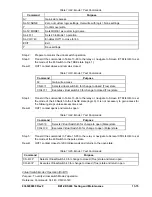
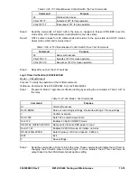
Prepare the 50BF function block for testing by transmitting the commands in Table 13-76 to
the relay.
Table 13-76. 50BF, BFI52 Contact Initiate Test Commands
Command
Purpose
A=
Gain write access
SL-N=NONE
Zero out custom logic settings. Overwrite with logic = None settings.
Y
Confirm overwrite
SL-N=50BF-CONTACT
Sets 50BF as custom logic name
SL-50BF=1,0,IN2,/IN1,0
Enables BF CT Input 1, Disable BFI50, IN2 = BFI52 initiate, /IN1 =
Breaker Position, No block
SL-VO1=BFT1
Enables OUT1 to close for BF Trip 1
SL-VO2=BFRT1
Enables OUT2 to close for BF Retrip 1
SG-CT=1,WYE,NA,0
Input 1 ctr = 1, ct = wye, xfmr = n/a, no ground source
SG-TRIGGER=BFT1,BFRT1,0
Enable BFT1 to log and trigger fault recording
S0-50BF=0,0,0,100m
Set Control Timer = 0, PFD & GFD = 0, BF time delay at minimum
EXIT
Exit
Y Save
settings
Step 2:
IN1 is used to simulate breaker status as supplied by a “b” contact from the circuit breaker.
With no wetting voltage applied to relay Input IN1, the relay considers the breaker closed as a
result of the /IN1 designation at the breaker status input of the breaker failure element. A
switched wetting voltage at IN2 is used to simulate an external BFI52 initiate contact for
starting the Breaker Failure Timer. This input is also used to start the test set timer and OUT1
of the relay is used to stop the test set timer. OUT2 should be monitored to verify operation of
the re-trip circuit upon breaker failure initiate.
Step 3:
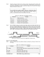
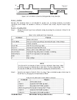
With no wetting voltage to relay Input IN1, switch on the wetting voltage to IN2 and measure
the operate time. Timer Accuracy = ±0.5% or
½ cycles), whichever is greater.
Step 4:
Apply wetting voltage to IN1 and repeat Step 3. There should be no operation.
Step 5:
Repeat Step 3 at 200 ms and 300 ms.
Step 6:
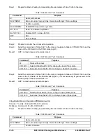
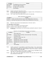
Repeat Steps 3, 4, and 5 for 150BF, 250BF, and 350BF. For 150BF use BFT2 and BFRT2.
For 250BF use BFT3 and BFRT3 and for 350BF use BFT4 and BFRT4. Make appropriate
changes in Table 13-76 for each element tested.
The following tests are for
Current Supervised relay trip initiates
. Any or all relay trips can
be used, 87R, 87U, 50T, 51, etc. For ease of testing, the 50TPT variable will be used in the
following tests.
Step 7:
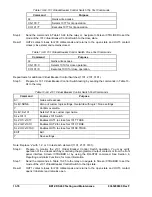
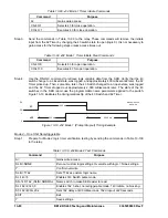
Prepare the 50BF function block for testing by transmitting the commands in Table 13-77.
Table 13-77. 50BF, BFI50 Current Supervised Relay Trip Initiate Test Commands
Command
Purpose
A=
Gains write access.
SL-N=NONE
Zero out custom logic settings. Overwrite with logic = none settings.
Y
Confirm overwrite.
SL-N=50BF-CURRENT
Sets 50BF as custom logic name.
SL-50BF=1,50TPT,0,0,0
Enables BF CT Input 1, 50TPT=BFI50 initiate, Disable BFI52 initiate,
Disable Breaker Position, No block.
SL-VO1=BFT1
Enables OUT1 to close for BF Trip 1.
Summary of Contents for BE1-CDS240
Page 2: ......
Page 8: ...vi BE1 CDS240 Introduction 9365200990 Rev F This page intentionally left blank ...
Page 38: ...1 28 BE1 CDS240 General Information 9365200990 Rev F This page intentionally left blank ...
Page 40: ...ii BE1 CDS240 Quick Start 9365200990 Rev F This page intentionally left blank ...
Page 152: ...ii BE1 CDS240 Metering 9365200990 Rev F This page intentionally left blank ...
Page 226: ...iv BE1 CDS240 Application 9365200990 Rev F This page intentionally left blank ...
Page 286: ...ii BE1 CDS240 Security 9365200990 Rev F This page intentionally left blank ...
Page 290: ...9 4 BE1 CDS240 Security 9365200990 Rev F This page intentionally left blank ...
Page 292: ...ii BE1 CDS240 Human Machine Interface 9365200990 Rev F This page intentionally left blank ...
Page 306: ...10 14 BE1 CDS240 Human Machine Interface 9365200990 Rev F This page intentionally left blank ...
Page 308: ...ii BE1 CDS240 ASCII Command Interface 9365200990 Rev F This page intentionally left blank ...
Page 342: ...11 34 BE1 CDS240 ASCII Command Interface 9365200990 Rev F This page intentionally left blank ...
Page 349: ...Figure 12 5 Horizontal Rack Mount Front View 9365200990 Rev F BE1 CDS240 Installation 12 5 ...
Page 361: ...Figure 12 17 Typical DC Connection Diagrams 9365200990 Rev F BE1 CDS240 Installation 12 17 ...
Page 372: ...12 28 BE1 CDS240 Installation 9365200990 Rev F This page intentionally left blank ...
Page 468: ...13 92 BE1 CDS240 Testing and Maintenance 9365200990 Rev F This page intentionally left blank ...
Page 512: ...14 42 BE1 CDS240 BESTCOMS Software 9365200990 Rev F This page intentionally left blank ...
Page 544: ...ii BE1 CDS240 Terminal Communication 9365200990 Rev F This page intentionally left blank ...
Page 550: ...ii BE1 CDS240 Settings Calculations 9365200990 Rev F This page intentionally left blank ...
Page 578: ...D 28 BE1 CDS240 Settings Calculations 9365200990 Rev F This page intentionally left blank ...
Page 579: ......


