


9365200990 Rev F
BE1-CDS240 Testing and Maintenance
13-73
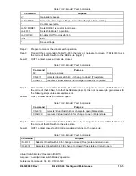
Command
Purpose
SL-VO2=BFRT1
Enables OUT2 to close for BF Retrip 1.
SA-LGC=5
Set Logic Alarm to BF1 Alarm (#5).
SL-VO3=ALMLGC
Enables OUT3 to close for BF1 Alarm.
SG-CT=1,WYE,NA,0
Input 1 ctr = 1, ct = wye, xfmr = n/a, no ground source.
SG-TRIGGER=BFT1,BFRT1,0
Enable BFT1 to log and trigger fault recording.
S0-50TP=2.0,0
Set pickup at 2 amps, 0 ms time delay.
S0-50BF=0m,1.0,1.0,50m
Set Control Timer =0 ms, PFD = 1 amp & GFD = 1amp, BF time
delay at minimum.
EXIT
Exit.
Y Save
settings
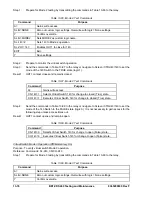
The BF current detector dropout setting (I=0 on BESTCOMS logic diagram) is a fixed value that is
determined by the relay current sensing type. Table 13-78 lists the pickup setting for each current sensing
type.
Table 13-78. BF Current Detector Dropout Settings
Sensing Type
Dropout Setting
A or B (1 ampere nominal systems)
90 mA
D, E, or F (5 ampere nominal systems)
450 mA
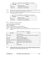
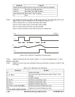
Step 8: In the current supervised Breaker Failure logic, load current must be above current detector
dropout settings (Table 13-75), fault current must be above Phase or Ground Fault Detector
setting (see Section 4 for range), fault current must be above the 50TP pickup setting to get a
BFI 50 initiate and all must occur within the set Control Time including Breaker Failure Time
Delay. If the Control Timer expires before BFT1 goes TRUE, BFT is blocked and the Breaker
Failure alarm becomes TRUE.
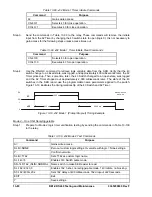
Step 9: Connect a current source to terminals A3 and A4 (A-phase input Current Circuit 1). Apply 50%
of nominal current to the relay and note operation of OUT1 and 2. Slowly decrease the current
applied until OUT2 (and subsequently OUT1) opens. Slowly increase current until OUT2
operates. Fault Detector Pickup should be +2% of setting and dropout should be 95% of
pickup.
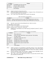
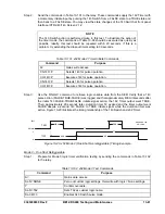
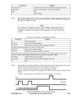
Step 10: Set Phase and Ground Fault Detectors at minimum. Repeat the dropout test in Step 9 to verify
current detector dropout. Compare the applied current to the current values listed in Table 13-
79. Verify that dropout occurred between the lower and upper limits for your relay.
Table 13-79. BF Dropout Limits
Sensing Type
Lower Dropout
Limit
Upper Dropout
Limit
A or B (1 ampere nominal systems)
0.09 A
0.11 A
D, E or F (5 ampere nominal systems)
0.45 A
0.55 A
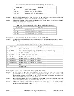
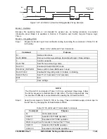
Step 11: Transmit the commands in Table 13-80 to set the BF time delay.
Table 13-80. BF Time Delay Commands
Command
Purpose
A=
Gains write access.
S0-50BF=100m,1.0,1.0,50m
Sets BF time delay at 100 milliseconds.
Summary of Contents for BE1-CDS240
Page 2: ......
Page 8: ...vi BE1 CDS240 Introduction 9365200990 Rev F This page intentionally left blank ...
Page 38: ...1 28 BE1 CDS240 General Information 9365200990 Rev F This page intentionally left blank ...
Page 40: ...ii BE1 CDS240 Quick Start 9365200990 Rev F This page intentionally left blank ...
Page 152: ...ii BE1 CDS240 Metering 9365200990 Rev F This page intentionally left blank ...
Page 226: ...iv BE1 CDS240 Application 9365200990 Rev F This page intentionally left blank ...
Page 286: ...ii BE1 CDS240 Security 9365200990 Rev F This page intentionally left blank ...
Page 290: ...9 4 BE1 CDS240 Security 9365200990 Rev F This page intentionally left blank ...
Page 292: ...ii BE1 CDS240 Human Machine Interface 9365200990 Rev F This page intentionally left blank ...
Page 306: ...10 14 BE1 CDS240 Human Machine Interface 9365200990 Rev F This page intentionally left blank ...
Page 308: ...ii BE1 CDS240 ASCII Command Interface 9365200990 Rev F This page intentionally left blank ...
Page 342: ...11 34 BE1 CDS240 ASCII Command Interface 9365200990 Rev F This page intentionally left blank ...
Page 349: ...Figure 12 5 Horizontal Rack Mount Front View 9365200990 Rev F BE1 CDS240 Installation 12 5 ...
Page 361: ...Figure 12 17 Typical DC Connection Diagrams 9365200990 Rev F BE1 CDS240 Installation 12 17 ...
Page 372: ...12 28 BE1 CDS240 Installation 9365200990 Rev F This page intentionally left blank ...
Page 468: ...13 92 BE1 CDS240 Testing and Maintenance 9365200990 Rev F This page intentionally left blank ...
Page 512: ...14 42 BE1 CDS240 BESTCOMS Software 9365200990 Rev F This page intentionally left blank ...
Page 544: ...ii BE1 CDS240 Terminal Communication 9365200990 Rev F This page intentionally left blank ...
Page 550: ...ii BE1 CDS240 Settings Calculations 9365200990 Rev F This page intentionally left blank ...
Page 578: ...D 28 BE1 CDS240 Settings Calculations 9365200990 Rev F This page intentionally left blank ...
Page 579: ......


